Sintered gear

a gear and friction technology, applied in the direction of mechanical equipment, transportation and packaging, hoisting equipment, etc., can solve the problems of noise, friction and contact on the engaging portion of the gear, and the strength of the gear is reduced in comparison

Active Publication Date: 2005-12-08
HITACHI POWDERED METALS COMPANY +1
View PDF8 Cites 23 Cited by
  • Summary
  • Abstract
  • Description
  • Claims
  • Application Information

AI Technical Summary

Benefits of technology

[0007] To solve the above-mentioned problem, a sintered gear of the present invention is a sintered gear composed of a sintered alloy having a metal matrix and pores, and a feature is to have a first densified layer that is formed on a tooth surface with a thickness of 300 to 1,000 microns and a ...

Problems solved by technology

This leads to a problem that strength of the gear is reduced in comparison with a general gear made of wrought steel having real density.
Use of a high-grade material and application of complicated manufacturing process are extremely disadvantageous in meeting t...

Method used


Image

  • Sintered gear
  • Sintered gear
  • Sintered gear

Examples


example 1

[0024] A graphite powder was added to a ferroalloy powder having a composition by mass ratio of Fe-0.5% Ni-0.5% Mo (grain size: 80 mesh) to prepare a mixed powder (composition: Fe-0.5% Ni-0.5% Mo-0.3% C) in which the ratio of the graphite powder was 0.3 percent by mass. The following operation was performed using this mixed powder as a raw material powder.

(Sample 1A)

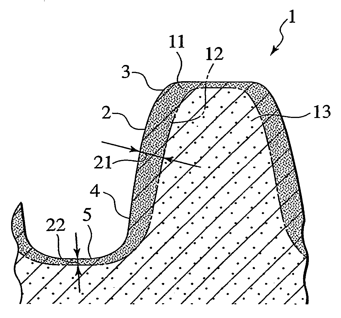
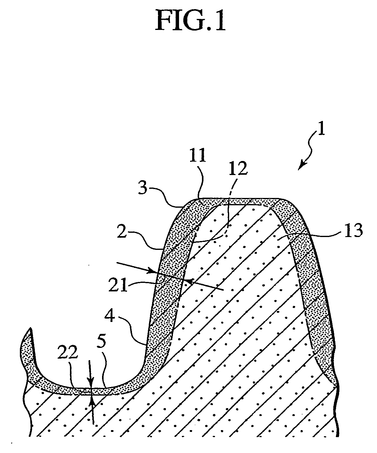
[0025] The raw material powder was pressed and compressed to form in a shape of a sprocket wheel. And it was sintered at 1,195 degrees C. to obtain a gear material. This gear material was subjected to a form rolling process and then heated at 900 degrees C. to obtain a sintered gear as Sample 1A having a densified layer as shown in FIG. 1 on the surface thereof. A form rolling allowance in the form rolling process was set to be 0.09 mm on the tooth surface and 0.02 mm on the bottom land and the tooth crest, and a form rolling pressure was set to be 3 ton.

[0026] As a result of measurement according to a measuring meth...

example 2

[0032] The same raw material powder as in Example 1 was subjected to the pressing, sintering, form rolling and heating processes according to the same method as that used for Sample 1A, excepting that the form rolling allowance in form rolling process was changed case by case in the range of 0.02 to 0.12 mm, to manufacture sintered gears (of Samples 2A to 2F) each having a densified layer of the thickness shown in Table 2 over the tooth surface, bottom land and tooth crest.

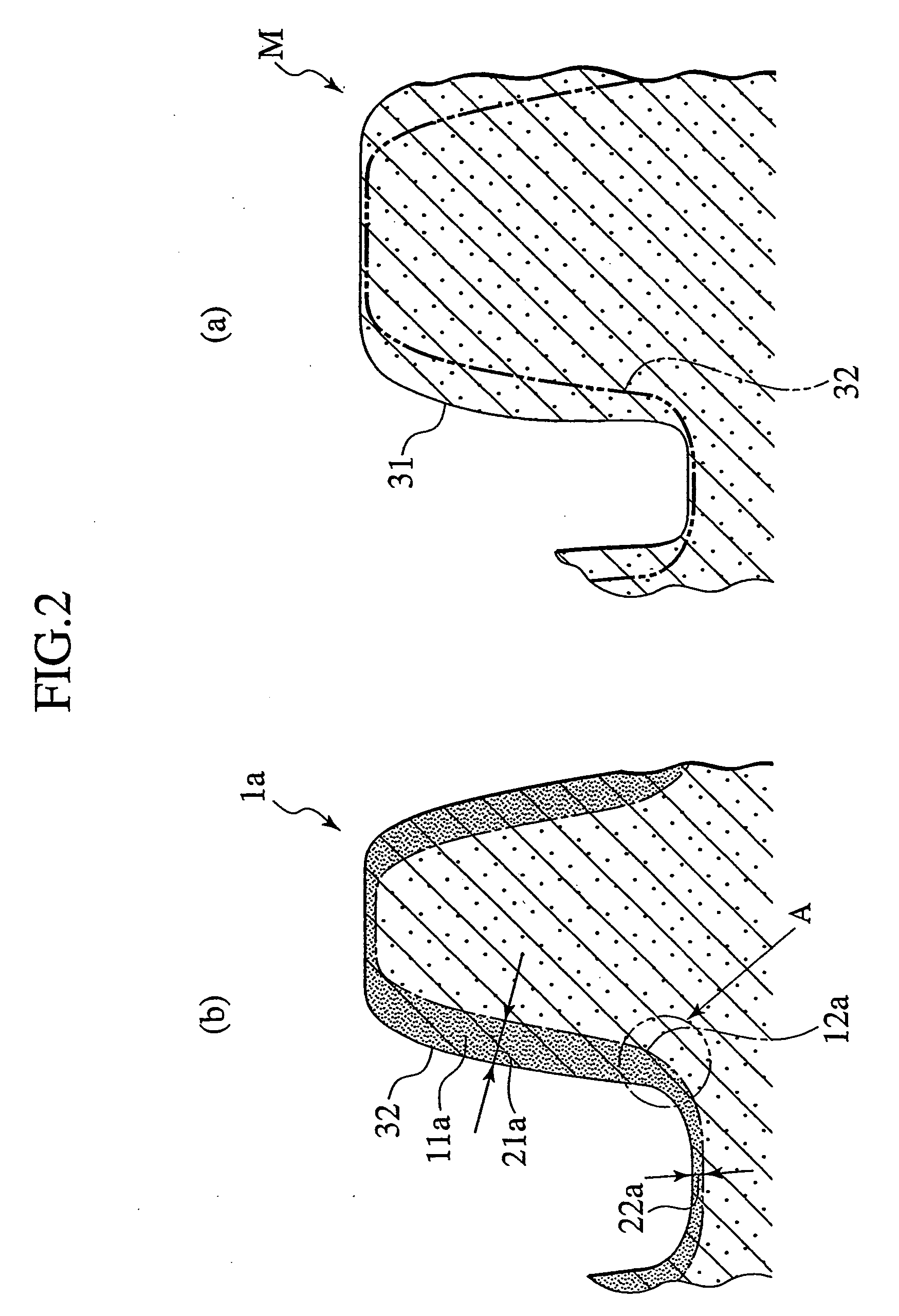
[0033] Moreover, a sintered gear of Sample 2B′ was manufactured by performing the pressing, sintering, form rolling and heating processes according to the same method as that used for Sample 2B, excepting that the shape of the sprocket of the formed compact had depression at its tooth flank as shown in FIG. 3.

[0034] For each of the sintered gears of Samples 2A to 2F, overall density was measured according to the same measuring method as that used for Sample 1A. As a result of measurement, overall density was fou...

example 3

[0038] The same raw material powder as in Example 1 was subjected to pressing, sintering, form rolling and heating processes according to the same method as that used for Sample 1A, excepting that the form rolling allowance in form rolling process was changed case by case in the range of 0 to 0.06 mm, to manufacture sintered gears (of Samples 3A to 3F) each having a densified layer of the thickness shown in Table 3 over the bottom land.

[0039] As a result of measurement according to the same measuring method as that used for Sample 1A, overall density of the sintered gears of Sample 3A to 3F was found to be 7.0 g / cm3, respectively. Moreover, density distribution and porosity of a metallographic cross-section of a tooth of the sintered gear were analyzed according to the same analyzing method as that used for Sample 1A. As a result, porosity of the densified layer was 2.5% over the outermost surface and 5% on average and porosity of the inner core portion was 13%, in each sample. Bou...


PUM

PropertyMeasurementUnit
Fractionaaaaaaaaaa
Thicknessaaaaaaaaaa
Lengthaaaaaaaaaa

Abstract

Disclosed is a sintered gear composed of a sintered alloy having a metal matrix and pores. The tooth surface (2, 3, 4) of the tooth and the bottom land (5) have a densified layer (11) in which the porosity is reduced to 10% or less from the sintered alloy. The densified layer at the tooth surface is formed with a thickness of 300 to 1,000 microns, and the densified layer at the bottom land is formed with a thickness of 10 to 300 microns. The boundary surface of the densified layer is continuous from the tooth surface side to the bottom land side so as not to have a substantial level difference.

Description

TECHNICAL FIELD [0001] The present invention relates to a sintered gear manufactured by compacting a metal powder and sintering the compacted matter, and includes general gears in which convex teeth engage with each other and power transmission vehicles such as chain wrapping vehicles. The present invention is particularly concerned with a sintered gear of which strength and noise reduction characteristics are required, and includes silent chain sprocket wheels. BACKGROUND ART [0002] Sintered gears are generally manufactured as follows: a metal powder is filled in a mold, which is compressed by the use of a punch in the vertical direction to form a compact; and the compact obtained in the shape of a gear is sintered. Since such a sintered gear can be manufactured in large quantities at low costs, sintered gears of various applications are commercially available as varied products. In the sintered gear, pores remain in a metal matrix due to the manufacturing method. Accordingly, dens...

Claims


Application Information

Patent Timeline
IPC IPC(8): B22F5/08F16H55/06F16H55/30
CPCB22F3/164B22F5/08B22F2998/00F16H55/30B22F3/1109B22F7/002B22F7/004Y10T428/249953Y10T428/12479Y10T74/19963Y10T428/12403Y10T74/19949
Inventor YAMANISHI, YUJISATO, RYOJIISHII, KEIARAKAWA, TOMOAKIYAMADA, JYUN-ICHITSUTSUI, TADAYUKIFUJIWARA, AKIRA
Owner HITACHI POWDERED METALS COMPANY
Why Eureka
Try Eureka