Tuple propagator and its use in analysis of mixed clock domain designs

a propagator and clock domain technology, applied in the field of semiconductor chip design, can solve problems such as difficult to identify exactly, inability to find signal convergence points in a reasonable duration of time, and acute problems

Active Publication Date: 2005-12-08
SYNOPSYS INC
View PDF11 Cites 19 Cited by
  • Summary
  • Abstract
  • Description
  • Claims
  • Application Information

AI Technical Summary

Benefits of technology

[0015] Tuple propagation starts from one or more elements (also called “starting elements”) in the circuit description (such as gates or flip-flops), proceeds through elements to which each starting element is immediately connected, and proceeds further through elements to which the just-described elements are immediately connected and so on, up to a predetermined depth in terms of elements that are clocked (also called “sequential depth”). During such propagation, if an element is not currently identified with any tuple, then the tuple being propagated is identified with the element. If the element is currently identified with at least another tuple, then a check is made as to whether the tuple being propagated differs from every tuple currently identified with the element.
[0016] If the result of the just-described check is true, then an operation (called “merge and reduce”) is performed between a first list that contains the tuple being propagated and a second list that is associated with the current element. During this operation, a combined list is formed to include non-redundant tuples from the two lists. Note that tuples are considered redundant (i.e. identical) if all information except sequential depth is identical. If the tuple be

Problems solved by technology

In such a circuit design, it is not easy to identify exactly where the signals Q1 and Q2 converge (or to identify whether or not they converge at all).
Conventional methods that have complexity on the order of N2 (where N is the number of gates) are unable to find points of signal convergence in a reasonab

Method used


Image

  • Tuple propagator and its use in analysis of mixed clock domain designs
  • Tuple propagator and its use in analysis of mixed clock domain designs
  • Tuple propagator and its use in analysis of mixed clock domain designs

Examples


Embodiment Construction

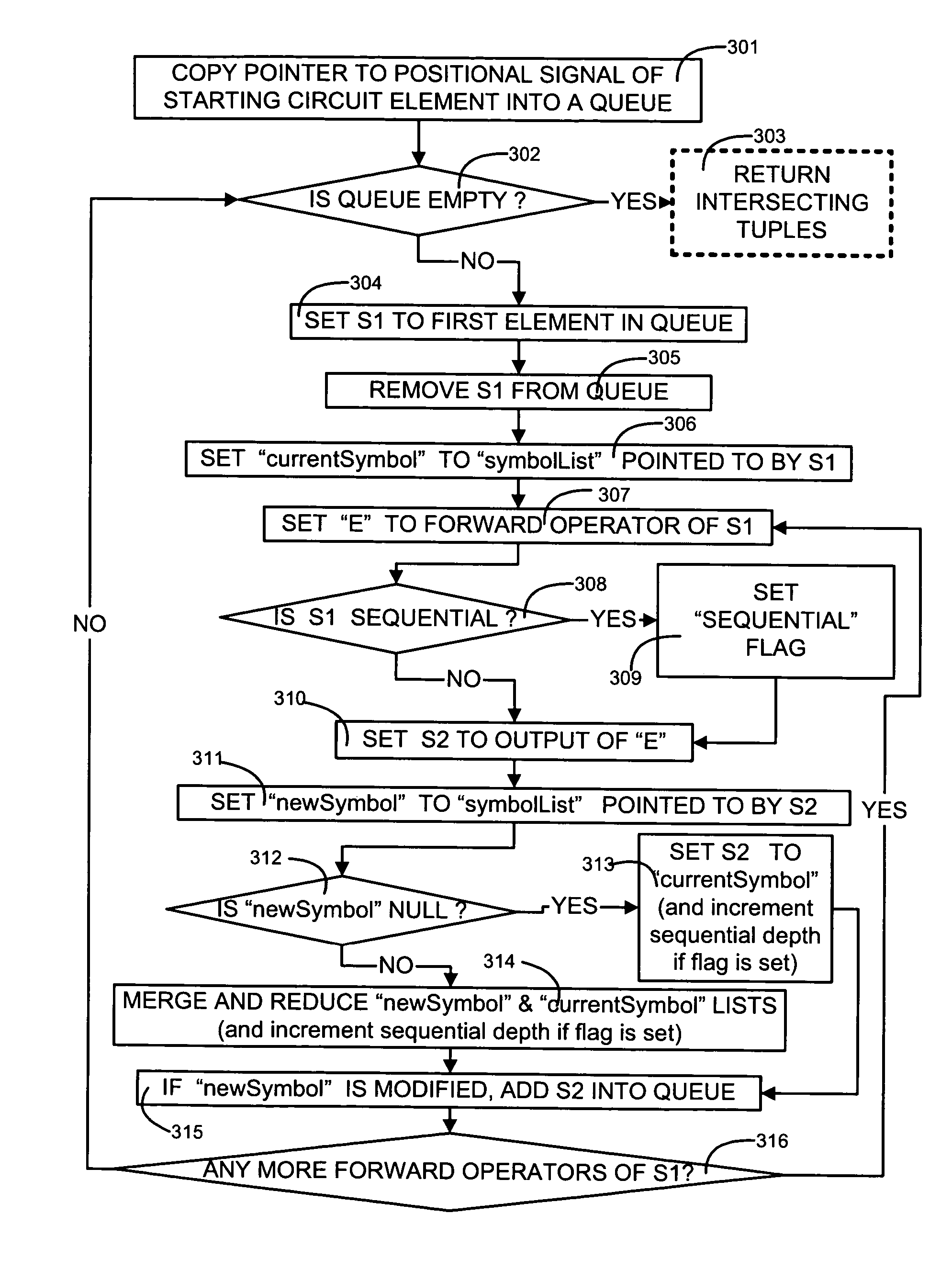
[0032] A computer is programmed in accordance with this invention to propagate in a digital circuit representation, at least a pair (which is a 2-tuple) of items namely: (a) name of a wire that carries a signal that crosses clock domains and (b) sequential depth of a circuit element from the boundary of the clock domain. Note that the programmed computer may propagate a pair of (signal / wire name and sequential depth) as a portion of an n-tuple (wherein n is any natural number greater than 1) that may or may not contain other information depending on the embodiment, such as the frequency at which the signal name being propagated was originally clocked prior to entering the current clock domain. Note that it is the name of the signal that is being propagated in accordance with the invention, and not the signal itself (e.g. a logic level of 0 or 1 is not propagated, but the name itself (such as “Q1”) is propagated).

[0033] Note that a representation of a circuit design (expressed in a ...


PUM


Abstract

Names of signals are propagated through a circuit design inside tuples, with each tuple including at least a signal name and a sequential depth. A tuple being propagated is added to a list of zero or more tuples currently identified with a circuit element, unless a tuple of the same signal name is already present in the list. If already present in the list, then propagation of that tuple is stopped. Propagation of tuples may also be stopped depending on user-defined limits, e.g. on sequential depth. Tuple propagation may be used, depending on the embodiment, to identify features of interest in the circuit design, e.g. (a) a point of convergence of differently clocked signals, (b) location of gray coders, and (c) location of synchronizers, by appropriate identification of circuit elements from which tuple propagation is to start, and by appropriate checks on lists of tuples that result from tuple propagation.

Description

CROSS-REFERENCE TO PROVISIONAL APPLICATION [0001] This application claims priority under 35 USC § 119(e) from a provisional application No. 60 / 577,318 filed on Jun. 3, 2004 having the title TUPLE PROPAGATOR AND ITS USE IN CONVERGENCE ANALYSIS, filed by Alain M. Dargelas, Attorney Docket SYN005 PV, which is incorporated by reference herein in its entirety.CROSS-REFERENCE TO COMPUTER PROGRAM LISTING APPENDIX [0002] Appendix A contains the following files in one CD-ROM (of which two identical copies are attached hereto), and is a part of the present disclosure and is incorporated by reference herein in its entirety. Volume in drive D is 040615_1241Volume Serial Number is E8CC-C7D9Directory of D:\06 / 15 / 2004 12:17p10,019 EMBOD1.TXT06 / 15 / 2004 12:16p12,362 EMBOD2.TXT06 / 15 / 2004 12:16p10,545 PROPGT.TXT3 File(s) 32,926 bytes0 Dir(s)0 bytes free The file PROPGT.TXT contains source code for a computer program written in the C++ language for a Tuple Propagator as described below. Files EMBOD1.T...

Claims


Application Information

Patent Timeline
IPC IPC(8): G06F17/50G06F11/00
CPCG06F17/5031G06F17/5059G06F30/35G06F30/3312
Inventor DARGELAS, ALAIN M.
Owner SYNOPSYS INC
Why Eureka
Try Eureka