Video monitoring system

a video monitoring and video monitor technology, applied in the field of video monitoring systems, can solve the problems of high cost of full-time guards, remote sites include costly equipment, and guards can miss certain events on video monitors, and achieve the effect of improving customer service capabilities

Inactive Publication Date: 2005-12-08
VISENTRY
View PDF8 Cites 204 Cited by
  • Summary
  • Abstract
  • Description
  • Claims
  • Application Information

AI Technical Summary

Benefits of technology

[0007] It is therefore an object of this invention to provide a video security system with greatly improved customer service capabilities.

Problems solved by technology

Employing full time guards is costly, however, and, in addition, guards can miss certain events on the video monitors due to distractions and / or fatigue.
The personnel at the remote site, however, still have to continuously monitor the video monitors for each site.
Also, the remote sites include costly equipment.
As such, central stations are costly.
Also, some present day remote site video event detection systems do not take full advantage of the internet as the communication interface between the site and the control station.
Other systems, for example, only begin video recording after an event is detected which means that the operator is unable to view the scene prior to the event.
In summary, the different technologies that are used today for behavior monitoring, access control, alarm detection, video compression, and the like are often complex and in most cases each technology was developed as a stand alone solution by a different entity and there is no natural connection and interface between all the current solutions.
No prior art teaches seamless integration between all of the various technologies to operate together.

Method used


Image

  • Video monitoring system
  • Video monitoring system
  • Video monitoring system

Examples


Embodiment Construction

[0035] Aside from the preferred embodiment or embodiments disclosed below, this invention is capable of other embodiments and of being practiced or being carried out in various ways. Thus, it is to be understood that the invention is not limited in its application to the details of construction and the arrangements of components set forth in the following description or illustrated in the drawings. If only one embodiment is described herein, the claims hereof are not to be limited to that embodiment. Moreover, the claims hereof are not to be read restrictively unless there is clear and convincing evidence manifesting a certain exclusion, restriction, or disclaimer.

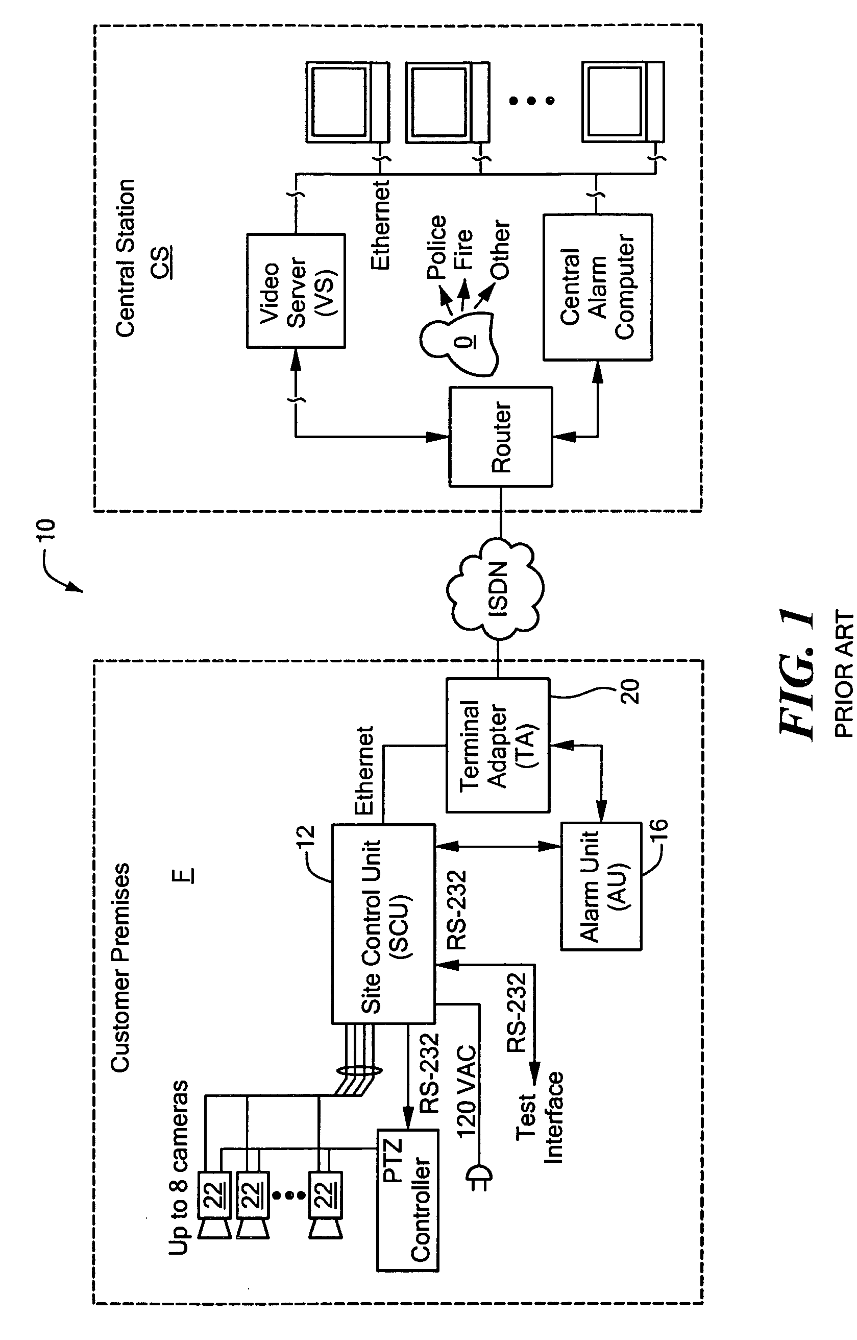
[0036]FIG. 1 depicts one state of the art video security system 10 as depicted in U.S. Pat. No. 6,069,655. The system informs operator O of the presence of an intruder at the facility F after detecting the intruder's presence and confirming the intruder is one of a designated class of intruders for which some action is to...


PUM


Abstract

A video monitoring system for a plurality of sites. A site security system is located at each site and includes one or more video cameras each outputting a video signal and a processor configured to receive a video signal from each camera, detect predetermined events based on the video signal, generate a video alarm signal upon the detection of an event, transmit the video alarm signal to a central station, and establish a video signal link either with the central station or one of a plurality of satellite stations according to a predetermined protocol upon the transmission of a video alarm signal. A central station includes a router for routing any received video signal to one or more workstations and for routing the video alarm signal to a server configured to associate the video alarm signal with a particular satellite station and to forward the video alarm signal to that satellite station. The satellite station includes a workstation configured to receive the video alarm signal from the central station and to receive the video signal from the site security system.

Description

FIELD OF THE INVENTION [0001] This invention relates to a video monitoring system including video event detection technology, a central station, and one or more satellite stations providing a less expensive and more secure monitoring solution for one or more customer sites with improved customer service. BACKGROUND OF THE INVENTION [0002] Video security systems have long been used in connection with office buildings and other business sites in conjunction with other security devices such as make / break contacts on doors, fire alarms, and many other types of sensors. Typically, a guard station at the site includes video monitors connected to a number of video cameras and viewed by one or more guards and a control panel which provides an indication when a sensor indicates an alarm condition. [0003] Employing full time guards is costly, however, and, in addition, guards can miss certain events on the video monitors due to distractions and / or fatigue. Thus, the idea of central control st...

Claims


Application Information

Patent Timeline
Patent Type & Authority Applications(United States)
IPC IPC(8): H04N7/18
CPCH04N7/181
Inventor SLOMOVICH, JUDAWIEDER, YONA
Owner VISENTRY
Why Eureka
Try Eureka