

Chain lock
- Summary
- Abstract
- Description
- Claims
- Application Information
AI Technical Summary
Benefits of technology
Problems solved by technology
Method used
Image

Examples
Embodiment Construction
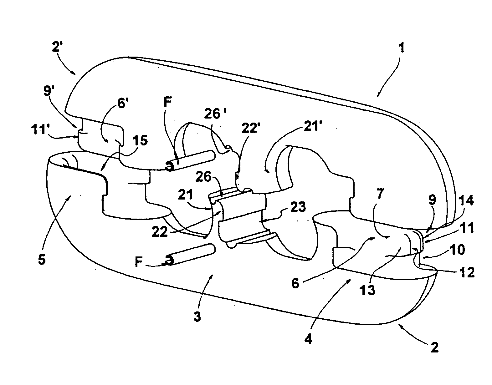
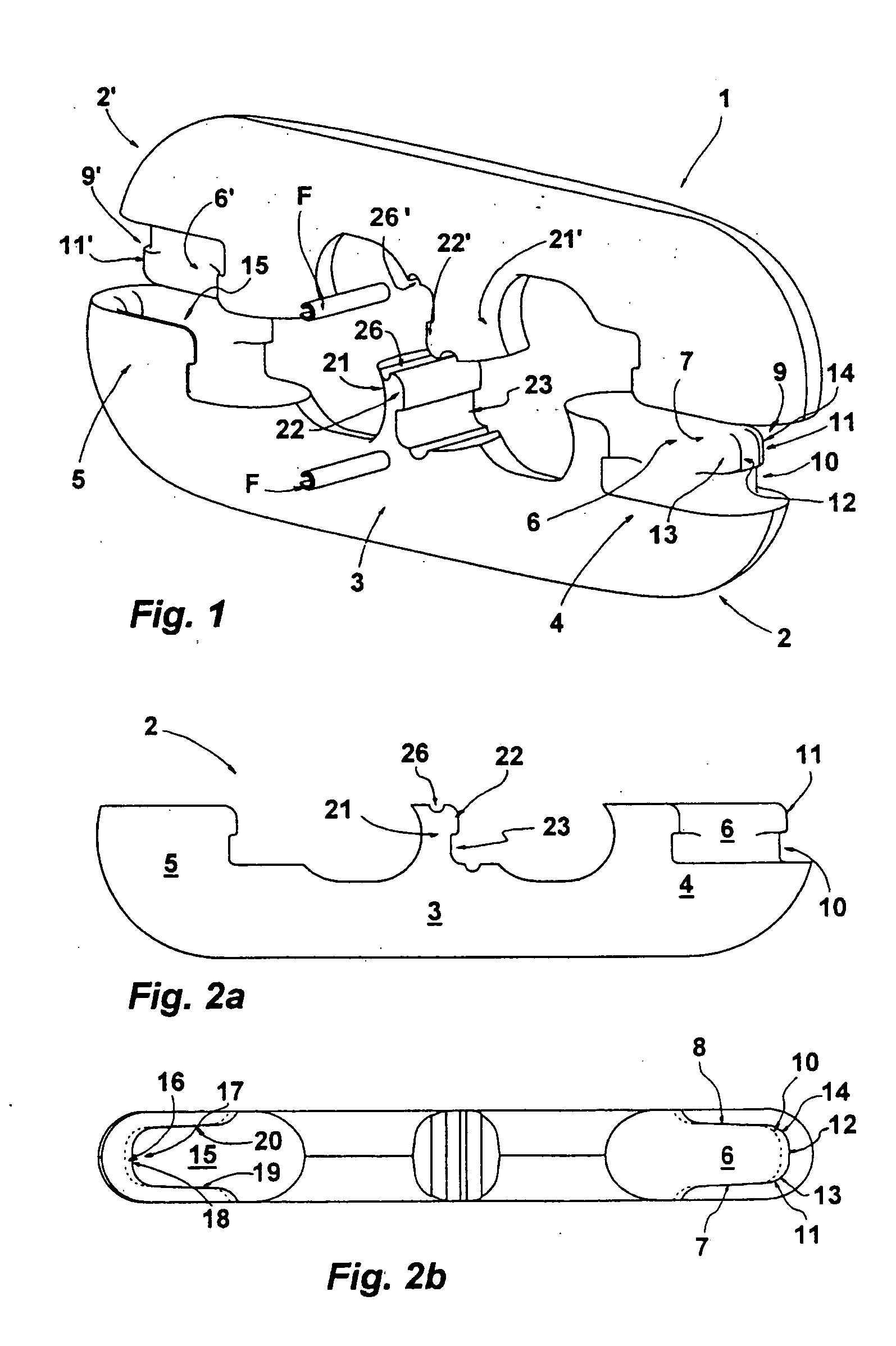
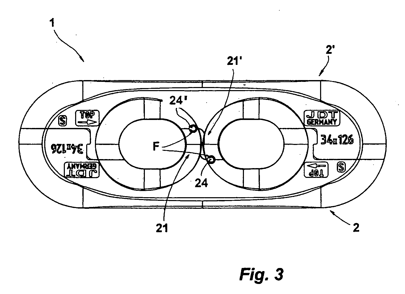
[0016] Referring now in detail to the drawings, there is shown a chain lock 1 for a high-strength steel chain, which consists of two lock parts 2, 2′. Lock parts 2, 2′ are structured identically with regard to their essential characteristics, which are described below, and are disposed with a rotational symmetry in the joining direction, relative to one another, in FIG. 1, to form the chain lock. In the following, the lock part 2 will be described in greater detail at first; the lock part 2′ has a corresponding structure.
[0017] Lock part 2 has a longitudinal stay 3, followed by an arc segment 4, 5 at both ends, in each instance. Arc segments 4, 5 have coupling elements with which lock part 2 can be connected with lock part 2′. The coupling elements of arc segments 4, 5 are configured to be complementary to one another. Arc piece 4, as a coupling element, bears a locking stay 6, the longitudinal expanse of which follows the longitudinal expanse of lock part 2. The locking stay is fo...
PUM
 Abstract
Description
Claims
Application Information