
Cycle pedal with adjustable axial positioning

Inactive Publication Date: 2005-12-15
LOOK CYCLE INT
View PDF16 Cites 30 Cited by
  • Summary
  • Abstract
  • Description
  • Claims
  • Application Information

AI Technical Summary

Benefits of technology

[0008] The invention has for its object to overcome these drawbacks by proposing a pedal provided with adjustment means of the transverse position of the cartridge which will be absolutely reliable as to the holding in place of this latter in the selected position and which moreover permits the use of a cartridge of plastic material. These holding means according to the invention are particularly simple to use and permit at the same time the easy and simple adjustment of the transverse position of the cartridge.

Problems solved by technology

However, the adjustment means comprise a large number of complicated pieces of which certain ones are relatively fragile.
Even if this pedal is generally satisfactory, it nevertheless has several drawbacks.
More precisely, it has been seen that in practice, this construction is not entirely reliable as to holding in place the cartridge in its recess.
This is due to the fact that the support comprising the recess of the cartridge is of deformable plastic material, which can give rise to a certain flow of this material under mechanical stress due to the gripping of the securement screws and as a result the impairment of the holding function.

Method used


Image

  • Cycle pedal with adjustable axial positioning
  • Cycle pedal with adjustable axial positioning
  • Cycle pedal with adjustable axial positioning

Examples


Embodiment Construction

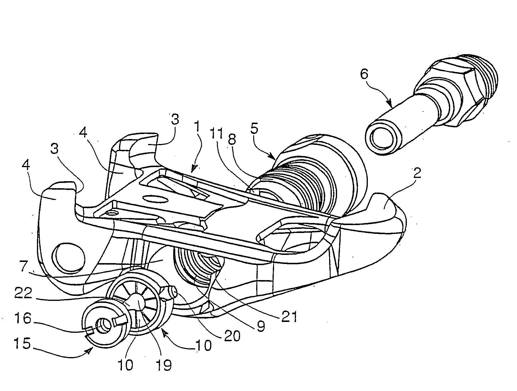
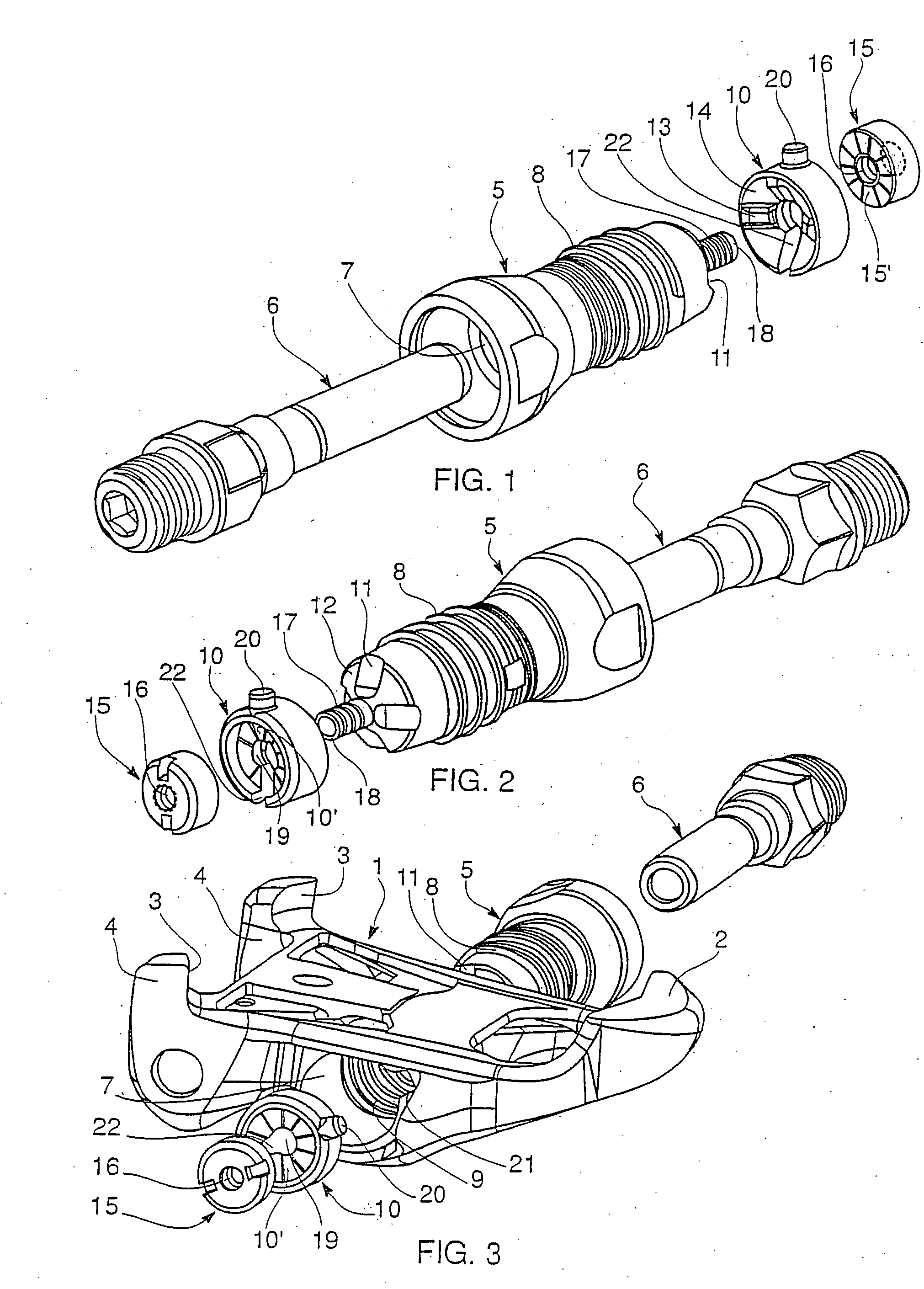
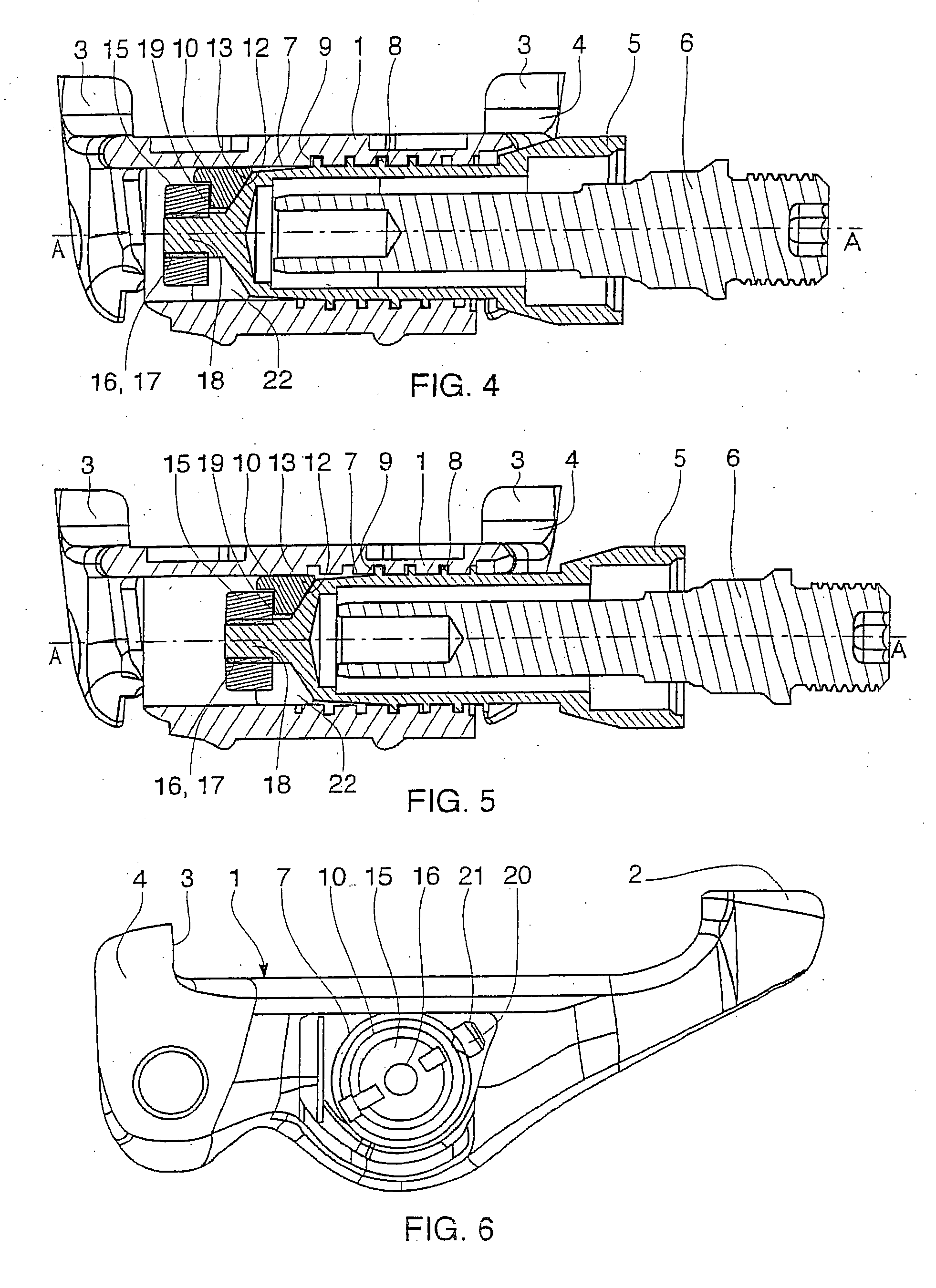
[0028] With reference to FIG. 3, the pedal comprises a pedal body 1 having engagement members with a hooking element (not shown) fixed below a cyclist's shoe (not shown). These engagement members comprise in a known manner a front fixed hook 2 and two rear movable hooks 3 formed on a respective lever 4 urged toward the engagement position by resilient elements constituted by torsion springs (not shown).

[0029] The pedal body moreover carries an elongated element in the form of a cartridge 5 in which a pedal axle 6 is rotatably mounted with the help of a roller bearing (not shown).

[0030] The pedal body 1 is provided with a transverse through hole of cylindrical shape forming a recess for the cartridge 5.

[0031] For the adjustment of the transverse position of the pedal body 1, and accordingly of the bearing surface for the foot, along the pedal axis A-A (see FIG. 4), the cartridge 5 is provided with a screw threading 8 adapted to coact with a tapping 9 provided on the internal wall ...


PUM


Abstract

The pedal comprises a pedal body having hooks, and a cartridge containing a pedal axle and which is received in a transverse recess of the pedal. This recess is provided with a tapping coacting with a screw, thread on the cartridge to permit the continuous adjustment of the transverse position of this latter, and holding elements of the cartridge in a transverse position. The holding elements comprise a ring for blocking in rotation the cartridge adapted to be connected to the cartridge by positive locking members provided on one end of the latter and positive locking members provided on the ring. Gripping elements are provided to grip the ring against the cartridge.

Description

FIELD OF THE INVENTION [0001] The present invention relates to automatic pedals with adjustable positioning of the pedal on the pedal axle, and more particularly roadway pedals, but also all terrain pedals. BACKGROUND OF THE INVENTION [0002] A pedal of this type comprises a pedal body having engagement members of a hooking element fixed below the cyclist's shoe, and a pedal axle adapted to be fixed to a pedal crank. [0003] There are known automatic pedals of this type permitting the adjustment of the positioning of the bearing surface of the foot during pedaling. A first adjustment permits moving transversely along the pedal axle the bearing surface of the foot on the pedal relative to the pedal crank to bring the foot as close as possible to this latter without touching it or to space it from the latter. A second adjustment can be provided so as to permit modifying the angle of inclination of the pedal body relative to the pedal axle. [0004] An automatic pedal permitting these adju...

Claims


Application Information

Patent Timeline
IPC IPC(8): B62M3/08B62M3/00G05G1/30
CPCB62M3/086Y10T74/2168Y10T74/217
Inventor REBOULLET, OLIVIER
Owner LOOK CYCLE INT
Features
  • Generate Ideas
  • Intellectual Property
  • Life Sciences
  • Materials
  • Tech Scout
  • Unparalleled Data Quality
  • Higher Quality Content
  • 60% Fewer Hallucinations
Learn More