Punching device and punching die for it

Inactive Publication Date: 2005-12-15
GROZ BECKERT KG
View PDF9 Cites 6 Cited by
  • Summary
  • Abstract
  • Description
  • Claims
  • Application Information

AI Technical Summary

Benefits of technology

[0012] Producing the punching die can be done with very short cycle times. A head blank need merely be slipped over the shaft and then secured on the shaft by a suitable deformation process for the plastic deformation of the head. The production processes with which this can be achieved are for example embossing, pressing, rolling, hammering, or other methods for non-metal-cutting shaping. If the head is of a metal with a low melting point, it could if necessary also be produced by a casting process, such as diecasting. However, this is considered to be less advantageous, because the effort involved is greater.
[0013] The protrusion that secures the head to the shaft is created, as noted, preferably by plastic deformation of the head blank. To that end, an indentation is embodied on the head in production. The shape of the indentation preferably corresponds to the shape of the recess provided on the shaft. If the recess is an annular bead, for instance, then an annular indentation is embodied on the otherwise cylindrical outer circumferential surface of the head. As a result, the requisite plastic deformation of the head is kept to a minimum. However, it is also possible to provide a supplementary counterholding or deforming pressure, for example in the axial direction against the head, in order to promote the radially inward-oriented inflow of head material into the recess of the shaft.
[0015] The head is preferably seated on the end of the shaft that is diametrically opposite the working part. It is preferably seated on the end of the shaft, so that the shaft end is flush with the head or protrudes slightly out of the head. It has proved advantageous for the recess and correspondingly the protrusion of the head that engages the recess to be disposed near the shaft end. The opening in the head, on the side facing away from the shaft end, thus has a cylindrical guide portion, which transmits tilting moments that engage the head to the shaft or is braced on the shaft without stressing the zone of the shaft that is weakened by the recess. This is particularly applicable if the recess in the shaft, as is preferably the case, is flush with the upper plane face, oriented toward the shaft end, of the head.
[0017] Besides securing the head to the shaft by positive engagement, connecting it by material engagement may also be provided. This may for instance be an adhesive connection or bond. The advantage of this provision is for instance the ease of introducing the adhesive, which can be accommodated in the recess of the shaft before the plastic deformation operation.

Problems solved by technology

However, this is considered to be less advantageous, because the effort involved is greater.

Method used


Image

  • Punching device and punching die for it
  • Punching device and punching die for it
  • Punching device and punching die for it

Examples


Embodiment Construction

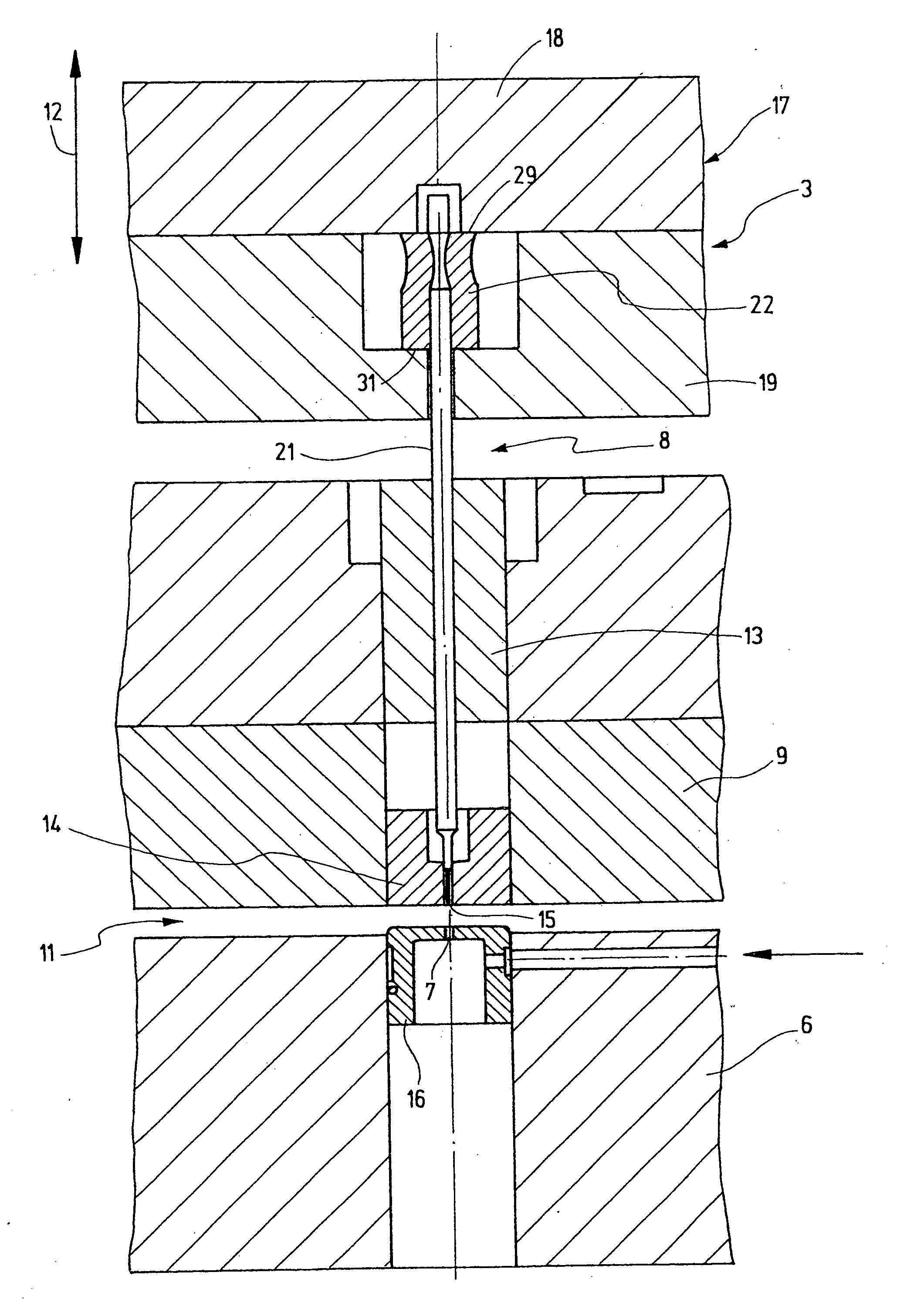
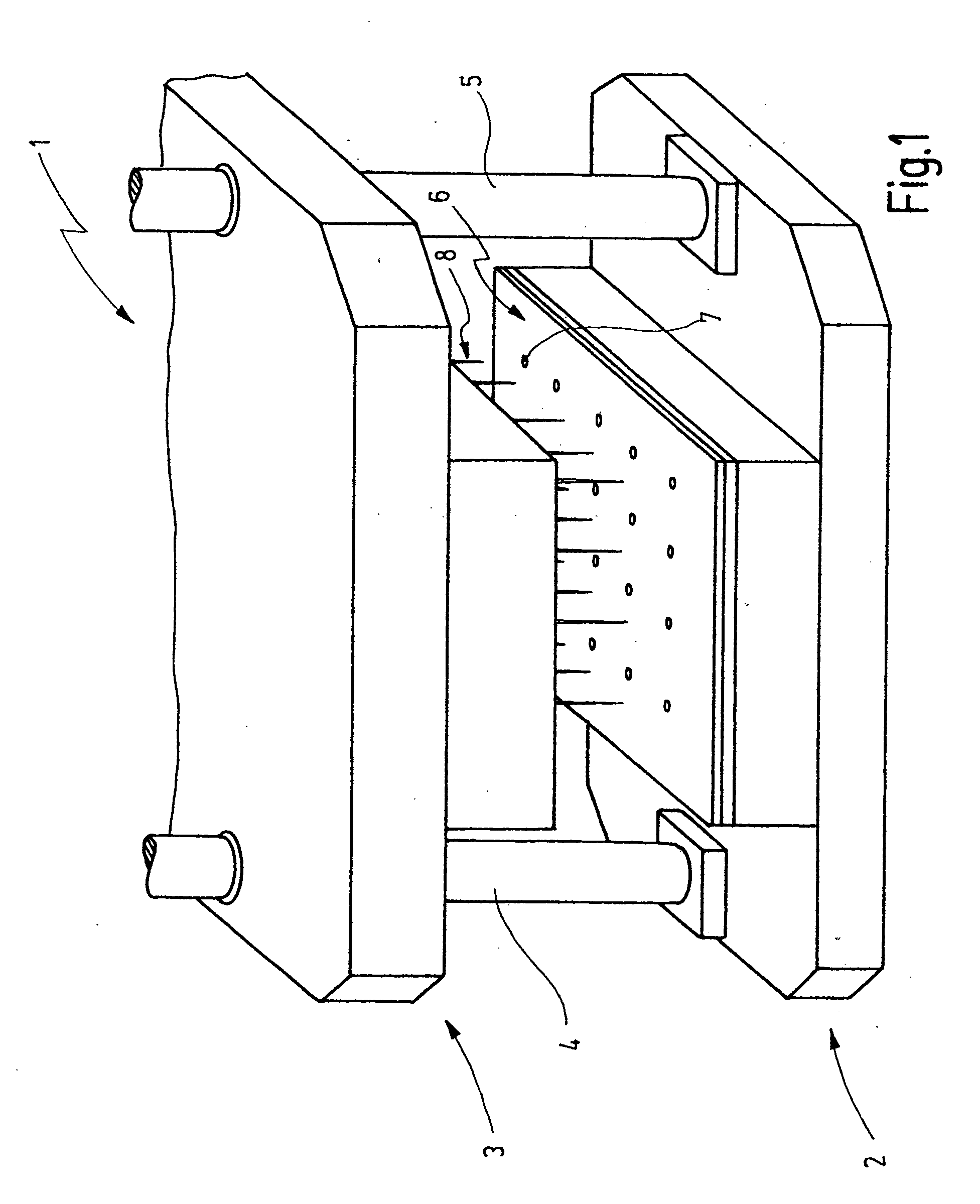
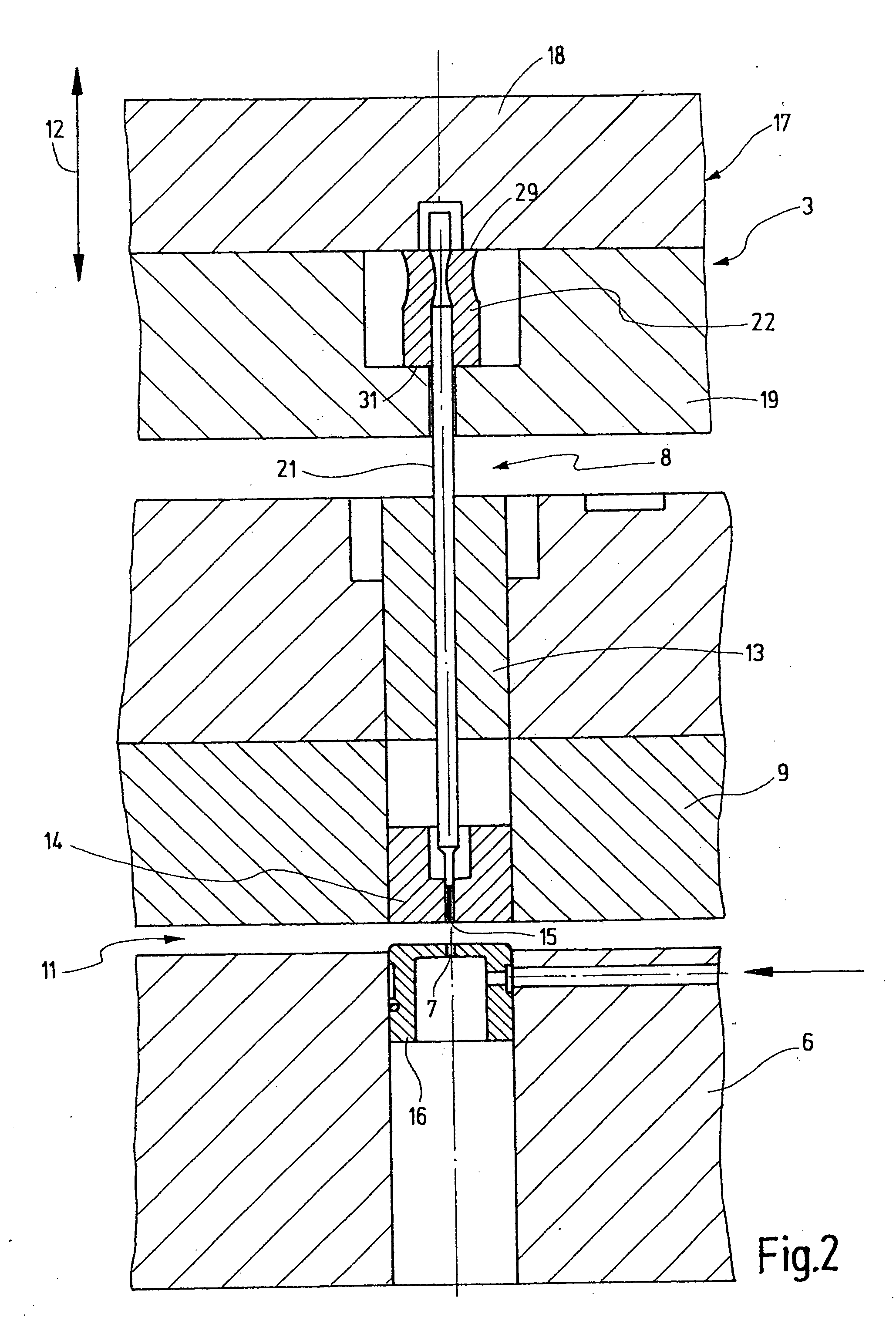
[0029] In FIG. 1, a punching tool 1 is shown, which includes a lower tool 2 and an upper tool 3. The upper tool 3 can be moved linearly back and forth by means of two guides 4, 5 toward the lower tool 2 and away from it. The lower tool 2 includes a bearing plate or receptacle device 6, in which punched holes 7 are embodied. The punched holes 7 are embodied in great numbers in the bearing plate 6 and are located at points where holes are to be punched out in a green sheet (unfired ceramic substrate) placed on the bearing plate 6. To that end, dies 8 are disposed on the upper tool 3; they point toward the lower tool 2 and end above the bearing plate 6. The dies 8 can plunge into the punched holes 7 when they are moved downward. Above the bearing plate 6, there is a holding-down plate 9 for guiding the dies 8 and holding down the green sheets resting on the bearing plate; the holding-down plate has been left out in FIG. 1 in order to provide a clear view on the punching dies 8 and the ...


PUM

PropertyMeasurementUnit
Pressureaaaaaaaaaa
Shapeaaaaaaaaaa
Areaaaaaaaaaaa

Abstract

The punching die of the invention has a head 22 held by positive engagement. The head 22 is held on the shaft 21 of the die 8 in that by means of plastic deformation, for instance by radial application of pressure, material is positively displaced radially inward, so that a protrusion 28 is embodied which rests over a large area on the wall of a recess 23. A more secure, more durable force transition is assured.

Description

CROSS REFERENCE TO RELATED APPLICATION [0001] This application claims the priority of German Patent Application No. 20 2004 009 138.0, filed on Jun. 9, 2004, the subject matter of which, in its entirety, is incorporated herein by reference. FIELD OF THE INVENTION [0002] The invention relates to a punching device and its punching die. In particular, the invention relates to a punching device and a punching die for unfired sheetlike ceramic substrates, in particular so-called green sheets. BACKGROUND OF THE INVENTION [0003] Green sheets must as a rule, in their production, be provided with a number of small holes that are later used for through-contacting conductors that are mounted on the ceramic substrates. These are relatively small holes, of markedly less than one millimeter in diameter, and such holes must be made in large numbers. The punching device has a correspondingly large number of punching dies. The punching dies are provided with heads that are held in a holding device, ...

Claims


Application Information

Patent Timeline
IPC IPC(8): B21D28/34B26F1/00B26F1/14H05K3/00
CPCB21D28/34Y10T83/943Y10T83/9428Y10T83/9476
Inventor HALAMODA, HANS-JOACHIMBEERHALTER, SIEGFRIED
Owner GROZ BECKERT KG
Why Eureka
Try Eureka