
Moving camera mount

a camera and mounting system technology, applied in the direction of machine supports, instruments, transportation and packaging, etc., can solve the problems of insufficient stiffness of the rails to be self-supporting, the limitations of the various methods of moving cameras, and the heavy weight of the typical dolly method for many applications, etc., to achieve the effect of reducing weigh

Inactive Publication Date: 2005-12-15
THIELTGARY
View PDF3 Cites 14 Cited by
  • Summary
  • Abstract
  • Description
  • Claims
  • Application Information

AI Technical Summary

Benefits of technology

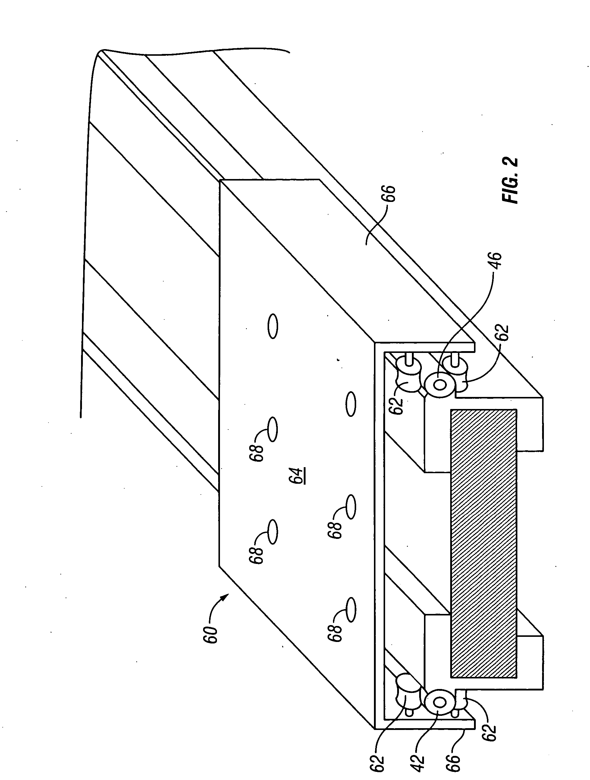
[0006] The current invention provides a rail system for example to be used with a moving camera platform sled that overcomes numerous limitations of previous rail systems and mounting methods. The weight and rigidity of the rail system along with its mounting capabilities allows the attachment of the rail system to moving objects such as automobiles, as well as other mounting applications such as overhead, along walls or in tight spaces. A radio controlled, motorized sled or camera mount fixed on the rail system can provide operational control where the direct operation of a dolly is unfeasible, such as for a camera suspended overhead or on a traveling vehicle. The motorized sled, along with its precise controls, allow the exact positioning of the camera along the rail system, as well as precise control of the speed of travel of the motorized sled between start and stop points along the rail system. The action of starting and stopping the sled can be precisely and repeatedly controlled through the operational controls. In this manner, the camera moves can be made with precision, speed and smooth starts and stops at preset positions and repeated so as to allow multiple repetitions of a specific film sequence during a filming session.
[0007] The camera may be mounted and leveled to the horizontal even though the rail system may be angled with respect to the horizon. The drive mechanism for the sled or camera mount may be on board the sled or incorporated into the rail system to provide a reduced weight in the case of cantilevered positioning of the rail system. Curved rails are also contemplated so the position may be varied through a radius in combination with straight-line travel.
[0008] The present invention thus generally provides a rail system and a variety of moving mounts, including, but not limited to, platforms, rails, harnesses and mounts. In one embodiment, the moving mount may be a light weight rigid camera platform and rail system that may be used, for example in the film industry, and may be affixed to a moving vehicle such as a car, boat, motorcycle or the like to provide a fixed camera mount or a linear or curvilinear motion to the camera mounting system. It may also be affixed overhead or to the floor or walls adjacent to the film subject thus enabling the camera to be moved during the photography and achieve changing perspective in relation to the subject being photographed.

Problems solved by technology

The limitations of these various methods of moving cameras are various.
Typical dolly methods are too heavy for many applications.
The rails are not stiff enough to be self-supporting.
Motorized versions of these tracks have been provided but are limited to a set length of travel and limited speed and mounting possibilities.
The lightweight arms that pivot from the base do not provide significant change of perspective to the vehicle to which they are mounted.

Method used


Image

  • Moving camera mount
  • Moving camera mount
  • Moving camera mount

Examples


Embodiment Construction

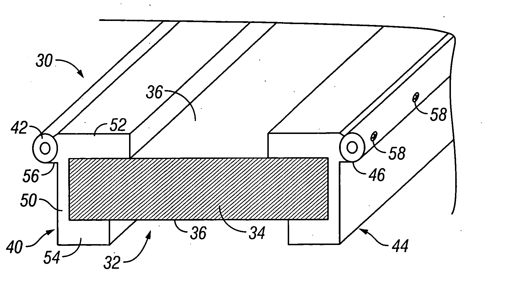
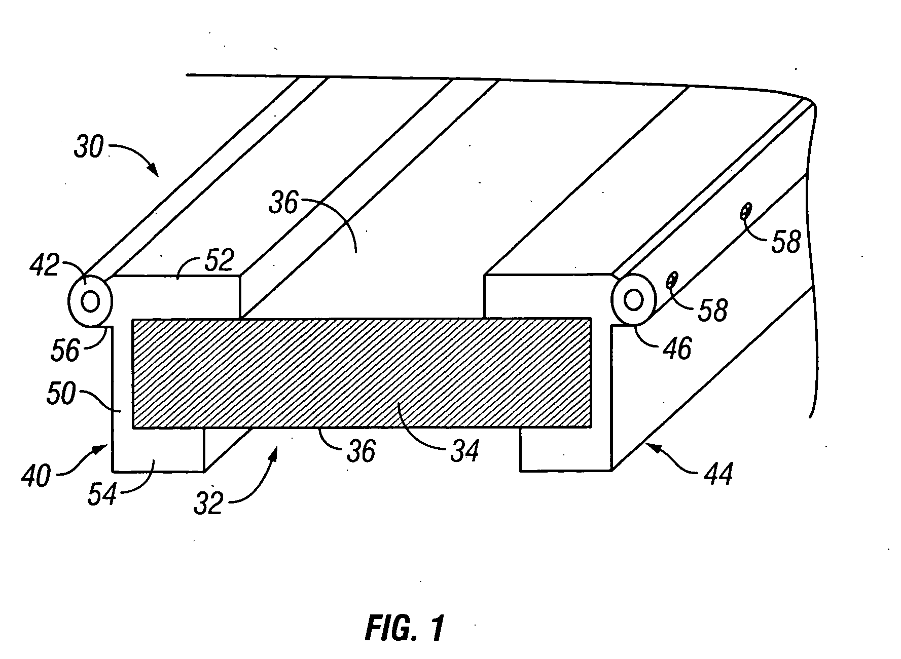
[0028] In preferred embodiments, the rail system comprises a rail 30 configured to receive a moving apparatus, such as sled having a platform for mounting a movie camera as shown in the multiple figures. As depicted in FIG. 1, the rail 30 comprises a core 32, positioned between a pair of opposing fixtures 40 and 44 for precision location of a pair of oppositely disposed shafts 42, 46 mounted on respective of the fixtures 40 and 44. The shafts 42, 46 extend along the length of the rail 30 in a longitudinal direction, wherein the shafts 42 and 44 are fixedly mounted on opposing sides of the rail 30 in which the core 32 resides.

[0029] Fixtures 40 and 44 are roughly ‘C’ shaped mirror image channels having a base 50, a top flange 52 and bottom flange 54. The top flange 52 and bottom flange 54 are spaced apart by the thickness of the core 32, so that the core 32 is captured in the ‘C’ shaped channel defined by the fixtures. A wedge 56, positioned opposite top flange 52 on the outer side ...


PUM


Abstract

A rail and an associated moveable sled for mounting equipment for example to be used with a moving camera platform. The weight and rigidity of the rail along with its mounting capabilities allows the attachment of the rail to moving objects such as automobiles, as well as other mounting applications such as overhead, along walls or in tight spaces.

Description

BACKGROUND OF THE INVENTION [0001] 1. Field of the Invention [0002] The present invention is directed to the field of movie camera mounting systems, although more generally the invention is directed to a light weight and highly rigid parallel rail track and slide or equipment platform sled system. [0003] 2. General Background and State of the Art [0004] The current methods of moving and mounting cameras in the motion picture industry are numerous and varied. Dollies have been used to move cameras in order to provide a changing perspective for nearly 100 years. Cranes and arms have been devised to extend the reach of the move. Mounts on cars have been provided to be able to capture images from fixed positions on a moving car. Lightweight arms have been provided to place the camera at distances off the vehicle. These arms have been articulated so as to provide a radius of movement from a pivot point at the base. Individuals have made custom one-use rigs to provide movement to cameras ...

Claims


Application Information

Patent Timeline
Patent Type & Authority Applications(United States)
IPC IPC(8): G03B15/00
CPCG03B15/00F16M11/18F16M11/2085F16M11/425
Inventor THIELTGES, GARY
Owner THIELTGARY
Learn More