Radiant heater in a cooking hob with a thermal switch

a technology of radiant heater and thermal switch, which is applied in the direction of heating fuel, thermal switch details, hot plate heating arrangement, etc., can solve the problems of low heater power, low sensor response time, and loss of correlation with the actual temperature of the plate area it has to detect, so as to achieve quick sensor response and not to respond to cooling.

Active Publication Date: 2005-12-15
EIKA S COOP LTDA
View PDF4 Cites 20 Cited by
  • Summary
  • Abstract
  • Description
  • Claims
  • Application Information

AI Technical Summary

Benefits of technology

[0010] The preferably bimetal type thermal switch is disposed in an air cavity within the heater under the cooking plate, wherein the heating resistors are mounted. In one embodiment of the invention the type of thermal switch used is a compact body bimetal sensor whose heat receiving side for the sensing element is directly facing the radiation of the heating resistors. Positioned in this way, the bimetal sensor is isolated from the influence of the external heating produced by the adjacent cooking hea

Problems solved by technology

Detecting the residual cooking plate temperature by means of a bimetallic sensor separated from the plate itself, as in the prior art solutions, presents the problem of the influence of the heat transmitted from adjoining heaters, which raises the ambient temperature and heats the peripheral wall of the heater.
This problem is particularly evident in the case of the so-called “warmer” type radiant heater, which is used solely for warming precooked foods or holding them at the maximum plate temperature of around 300° C. The power of the heater is low compared with the adjoining cooking heaters of the same hob, which heat their respective hob area

Method used


Image

  • Radiant heater in a cooking hob with a thermal switch
  • Radiant heater in a cooking hob with a thermal switch
  • Radiant heater in a cooking hob with a thermal switch

Examples


Embodiment Construction

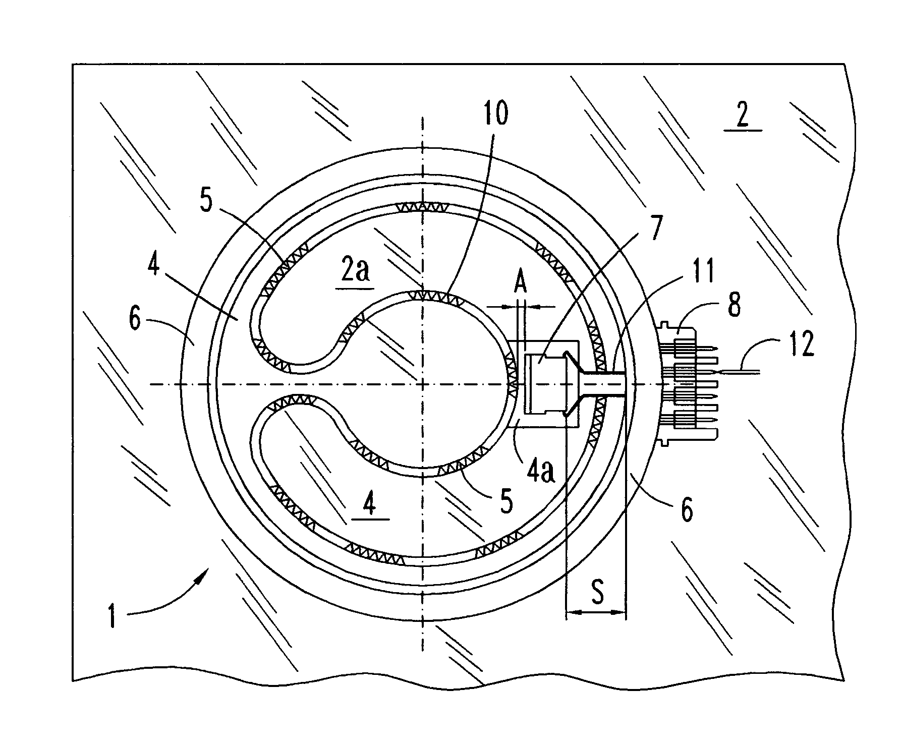
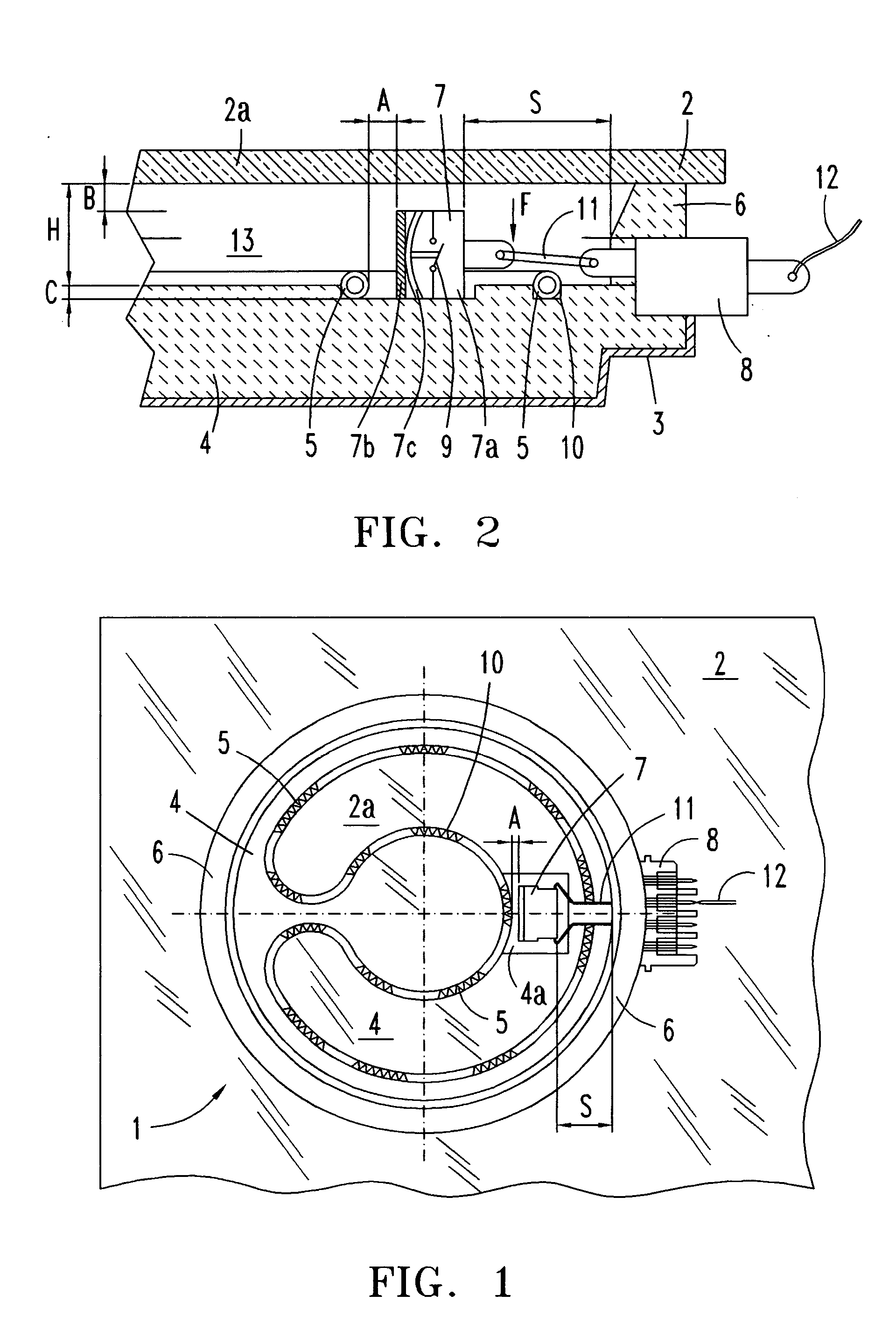
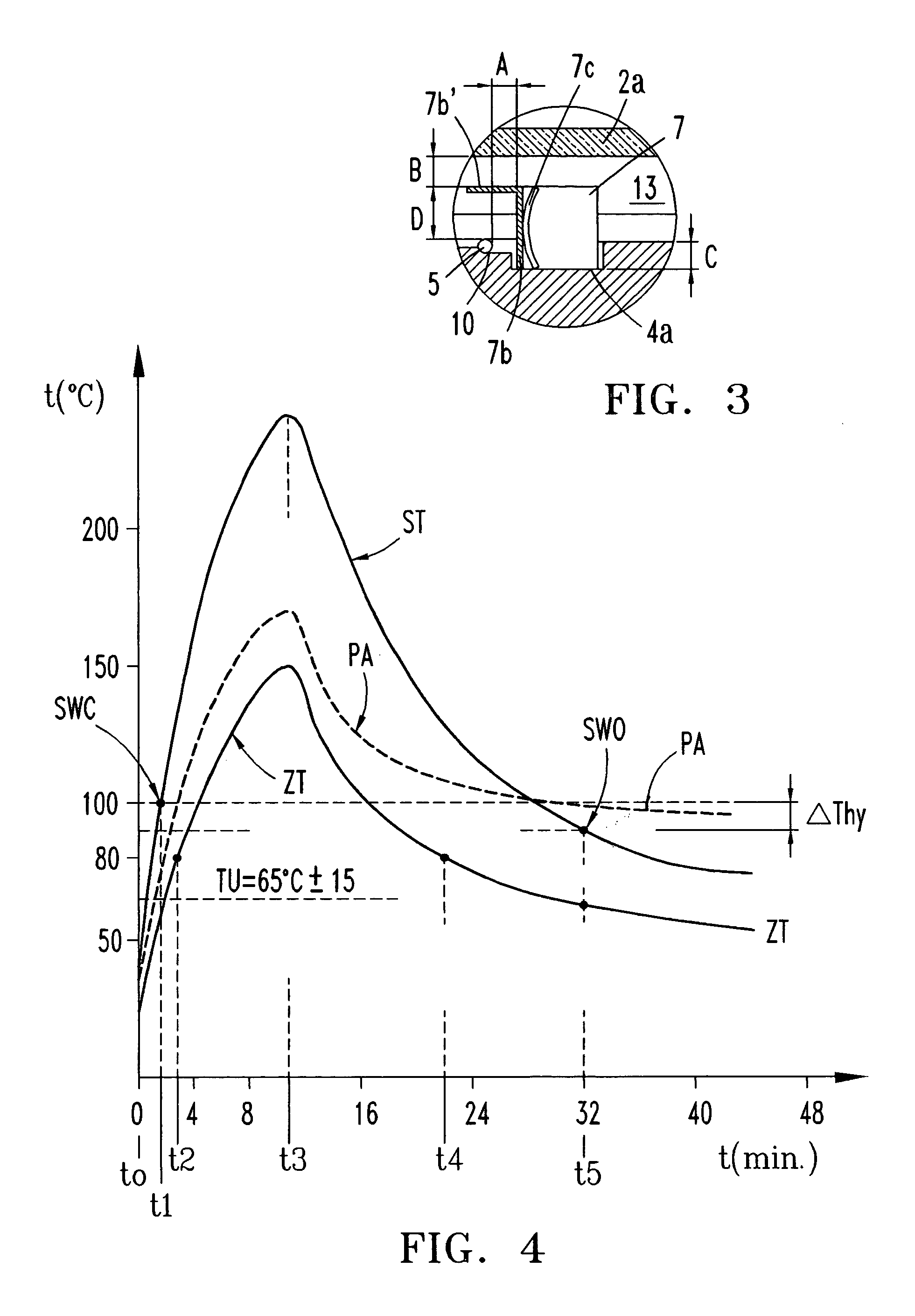
[0016] In reference to FIGS. 1-3, a preferred embodiment of radiant heater 1 is attached to the heating plate 2 of a cooking hob with various radiant heaters next to one another (not shown in the drawings) and it is made up of a cover or metal tray 3, an insulating base 4 carrying the heating resistors 5, a peripheral insulating ring 6 in contact with the cooking plate, a compact thermal switch or bimetal sensor 7 disposed in an air cavity 13 formed below the heated plate area 2a, between the insulating base 4 and the insulating ring 6, and an electrical connector 8 that transmits the power to the heating resistors 5 directly. The bimetallic sensor 7 has a compact electrical insulating body 7a, with an external metal base 7b on one side, which is exposed to direct radiation from at least one heating resistor 5, and a temperature-sensitive bimetal disc 7c housed in the receiver side of the body 7a, which actuates an electrical contact 9 of the normally open sensor, whose closure swit...


PUM


Abstract

The electric radiant heater (1) adapted to a cooking hob is attached to the cooking plate (2a) forming with it an air cavity (13) inside which the extended heating resistor (5) is housed on an insulating base (4). A peripheral insulating ring (6) and an outer metal tray form a peripheral external wall (3,6) defining said cavity (13) in which there is positioned a bimetal thermal switch (7), which has a compact body (7a) resting on the surface (4a) of the insulating base, and a heat receiver base (7b) in a position facing a part of the heating resistor (5). The position of the compact body (7a) relative to the heating resistor (5) is determined so as to obtain an actuating temperature point (SWC, SWO) adjusted for switching a hotplate warning light on and off.

Description

TECHNICAL FIELD [0001] The present invention is related to a radiant heater for an electric cooking hob, provided with a thermal switch for turning on and off a warning lamp to indicate the state of the hot plate during heating and cooling. PRIOR ART [0002] Radiant heaters of the above-mentioned type are known, with a built-in thermal switch whose electrical contact is used for switching on a warning lamp indicating that the cooking plate is still “hot” with a hazardous residual temperature, the threshold of which is set at 60-70° C. The thermal switch has to switch the warning contact during the onset of the heating of the cooking plate as well as during cooling to warn of a residual temperature higher than the aforesaid threshold value. The bimetallic sensor does not make direct contact with the hot plate, but the switch response time should be correlated to the actual temperature of the plate. For this purpose the thermal switch is situated on an area of the heater to receive pro...

Claims


Application Information

Patent Timeline
IPC IPC(8): F24C7/04F24C15/10H05B3/02H05B3/68
CPCH05B3/68H05B2213/04
Inventor TOYOS, DANIEL DE LOSAZPIRITXAGA, JON ENDIKA
Owner EIKA S COOP LTDA
Why Eureka
Try Eureka