Q enhancement circuit and method

a technology of enhancement circuit and enhancement circuit, applied in the field of electrical and electronic circuits and systems, can solve the problems of circuit delay, circuit resonance at other frequencies, negative resistor circuit not adequately canceling the parasitic resistance of inductors, etc., and achieve the effect of optimal circuit simplicity and maximum operating bandwidth

Inactive Publication Date: 2005-12-15
RAYTHEON CO
View PDF13 Cites 5 Cited by
  • Summary
  • Abstract
  • Description
  • Claims
  • Application Information

AI Technical Summary

Benefits of technology

[0013] In the best mode, each of the unity gain amplifier is a emitter / source follower to achieve optimal circuit simplicity and maximal operating bandwidth.

Problems solved by technology

Generally, the negative resistor circuits fail to adequately cancel the parasitic resistance of the inductors.
This non-ideal cancellation causes other second order effects and can cause the circuit to resonate at other frequencies.
This makes the negative resistor circuit more susceptible to non-linear distortion and circuit delay and degrades the performance of the LC resonator.

Method used


Image

  • Q enhancement circuit and method
  • Q enhancement circuit and method
  • Q enhancement circuit and method

Examples


Embodiment Construction

[0021] Illustrative embodiments and exemplary applications will now be described with reference to the accompanying drawings to disclose the advantageous teachings of the present invention.

[0022] While the present invention is described herein with reference to illustrative embodiments for particular applications, it should be understood that the invention is not limited thereto. Those having ordinary skill in the art and access to the teachings provided herein will recognize additional modifications, applications, and embodiments within the scope thereof and additional fields in which the present invention would be of significant utility.

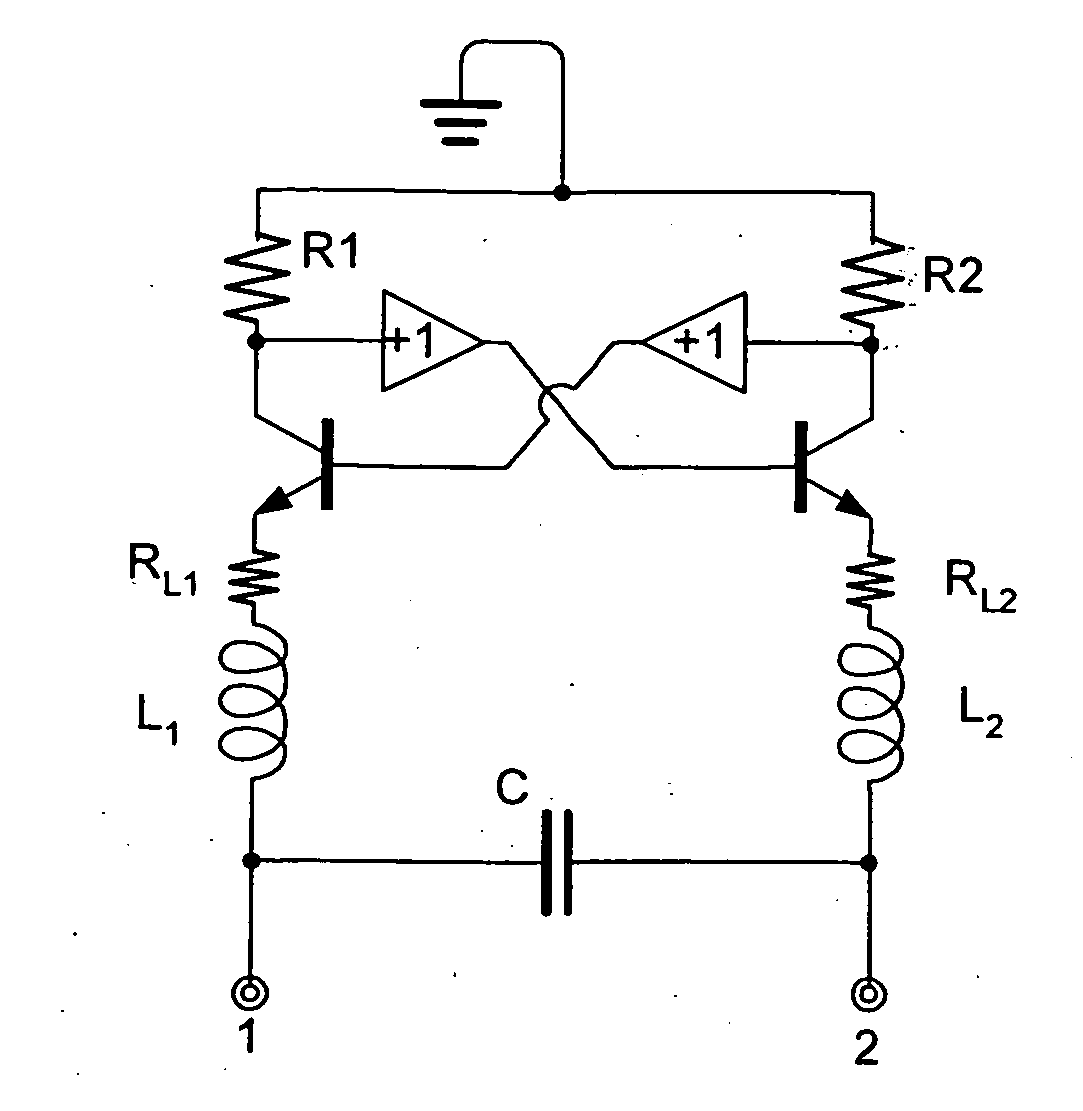
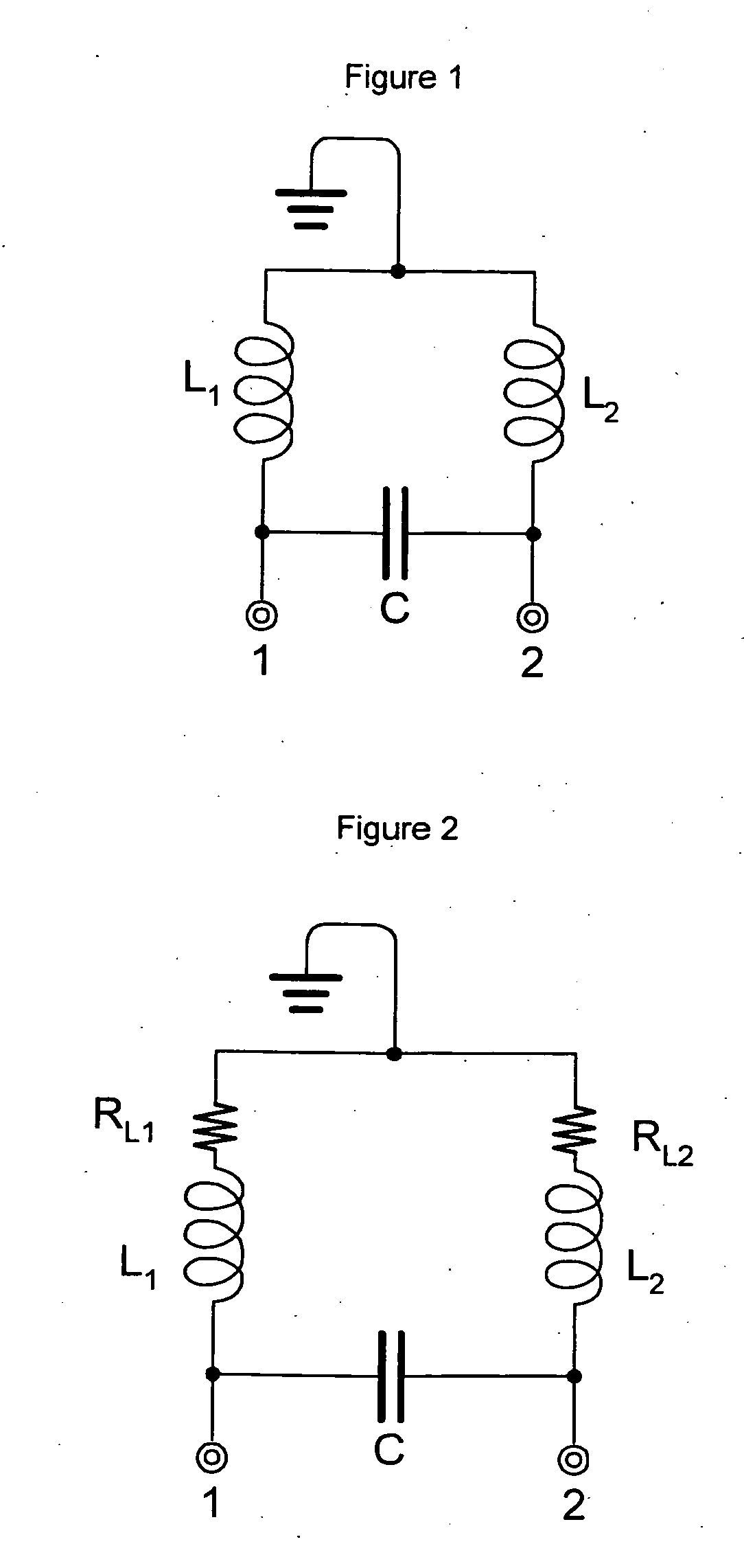
[0023]FIG. 1 is a schematic diagram showing a differential LC resonator widely used for analog signal processing in accordance with conventional teachings. FIG. 2 is a schematic diagram of the resonator of FIG. 1 showing parasitic resistance of the inductors thereof. As shown in FIGS. 1 and 2, the resonator 10′ includes first and second inductors...


PUM


Abstract

A Q enhancement circuit and method. In a most general embodiment, the inventive circuit is adapted for use with a component having a parasitic resistance R3 and a first resistance R1 disposed in series with the component and an arrangement for making the resistance a negative resistance. In the illustrative embodiment, first and second inductors constitute the components for which Q enhancement is effected. A resistance R1 is disposed in series with the first inductor and is equal to the parasitic resistance RL1 thereof. Likewise, a second resistance R2 is disposed in series with the second inductor and is equal to the parasitic resistance RL2 thereof. The Q enhancement circuit further includes a first transistor Q1 and a second transistor Q2.

Description

BACKGROUND OF THE INVENTION [0001] 1. Field of the Invention [0002] The present invention relates to electrical and electronic circuits and systems. More specifically, the present invention relates to systems and methods for Q enhancement for passive inductive capacitive resonators in electrical and electronic circuits and systems. [0003] 2. Description of the Related Art [0004] In reference to a resonant mechanical or electrical circuit or a capacitor, Q is a “quality factor.” In the case of a resonant system, Q is a measure of the sharpness of the resonant peak in the frequency response of the system and is inversely proportional to the damping in the system: Q=center frequency divided by Hz bandwidth. Equalizers that contain resonant circuits are rated by their Q-value: the higher the Q, the higher and more well defined the peak in the response. In filters, the ratio of a bandpass or band-reject filter's center frequency to its bandwidth defines Q. Thus, assuming a constant cente...

Claims


Application Information

Patent Timeline
Patent Type & Authority Applications(United States)
IPC IPC(8): H03H11/10H03H11/52
CPCH03H7/03H03H11/10H03H11/52
Inventor LUH, LOUIS
Owner RAYTHEON CO
Why Eureka
Try Eureka