Method and device for energy generation

a technology of energy generation and energy density, applied in the direction of electric generator control, machines/engines, generators/motors, etc., can solve the problems of high cost associated with tower height, increased cost of wind turbines, and towers that need to be very tall, so as to achieve high power and force delivery, large operating bandwidth, and high energy density

Inactive Publication Date: 2011-05-17
OSCILLA POWER
View PDF14 Cites 5 Cited by
  • Summary
  • Abstract
  • Description
  • Claims
  • Application Information

AI Technical Summary

Benefits of technology

Embodiments described herein include a method and device for converting the kinetic energy of wind into magnetic and / or electrical energy using novel designs that utilize magnetostrictive elements. Magnetostrictive materials have the property that when a strain is imposed on these materials, it results in a change in magnetization (or flux density) of an associated magnetic field. The phenomenon of magnetostriction has been known for over a century, but the field was really revolutionized by the discovery of giant magnetostrictive (Tb,Dy) alloys for use at cryogenic temperatures in the 1960s. Subsequently, giant magnetostrictive materials that work at room temperature including (Tb,Dy) and Terfenol alloys were developed. (Tb,Dy) and Terfenol-D alloys have saturation strain values as high as 10−2 (10,000 ppm) and 2×10⁻³ (2000 ppm), respectively, allowing for the development of many practical applications including torque sensors and high precision actuators. Magnetostrictive materials show changes in linear dimensions when a magnetic field is applied (Joule magnetostriction) and a reciprocal effect of changes in the magnetic properties with the application of stress. These characteristics make it possible to use magnetostrictive materials to function as both actuators and as sensors. They are analogous to piezoelectric materials, but have a large operating bandwidth extending to low frequencies, higher energy density, and capability for higher power and force delivery. For certain embodiments of this particular application, magnetostrictive materials are superior to piezoelectric materials due to their greater mechanical durability and lower production cost in high volumes.

Problems solved by technology

While wind power adoption has been increasing, there are still issues to be overcome before it can be cost competitive with conventional power on its own merit, without government subsidies or tax credits.
One of the issues is the high cost associated with tower height.
Due to the inability to harvest sufficient energy at low wind-speeds (i.e., low heights) using conventional designs, the towers need to be very tall as wind speeds are greater at higher altitude.
Unfortunately, this requirement can increase the cost of a wind turbine substantially.
Furthermore, these tall turbines require expensive cranes and skilled operators.
Increased tower height also increases maintenance costs as cyclic stress, fatigue and vibration tend to cause failure more frequently in taller turbines.
Tower height can even increase public relations costs as taller turbines are likely to increase complaints from residents about damage to their landscape views.
Another problem with conventional wind-turbines is the technology's low capacity factor.
The idle time results in an effectively high cost of energy, and a resulting problem with these types of turbines is that they are typically not used as primary power sources due to the unreliability of the power output.
The gearbox results in mechanical energy loss, unacceptable component failure rates, and a relatively high cut-in speed requirement.

Method used


Image

  • Method and device for energy generation
  • Method and device for energy generation
  • Method and device for energy generation

Examples


Embodiment Construction

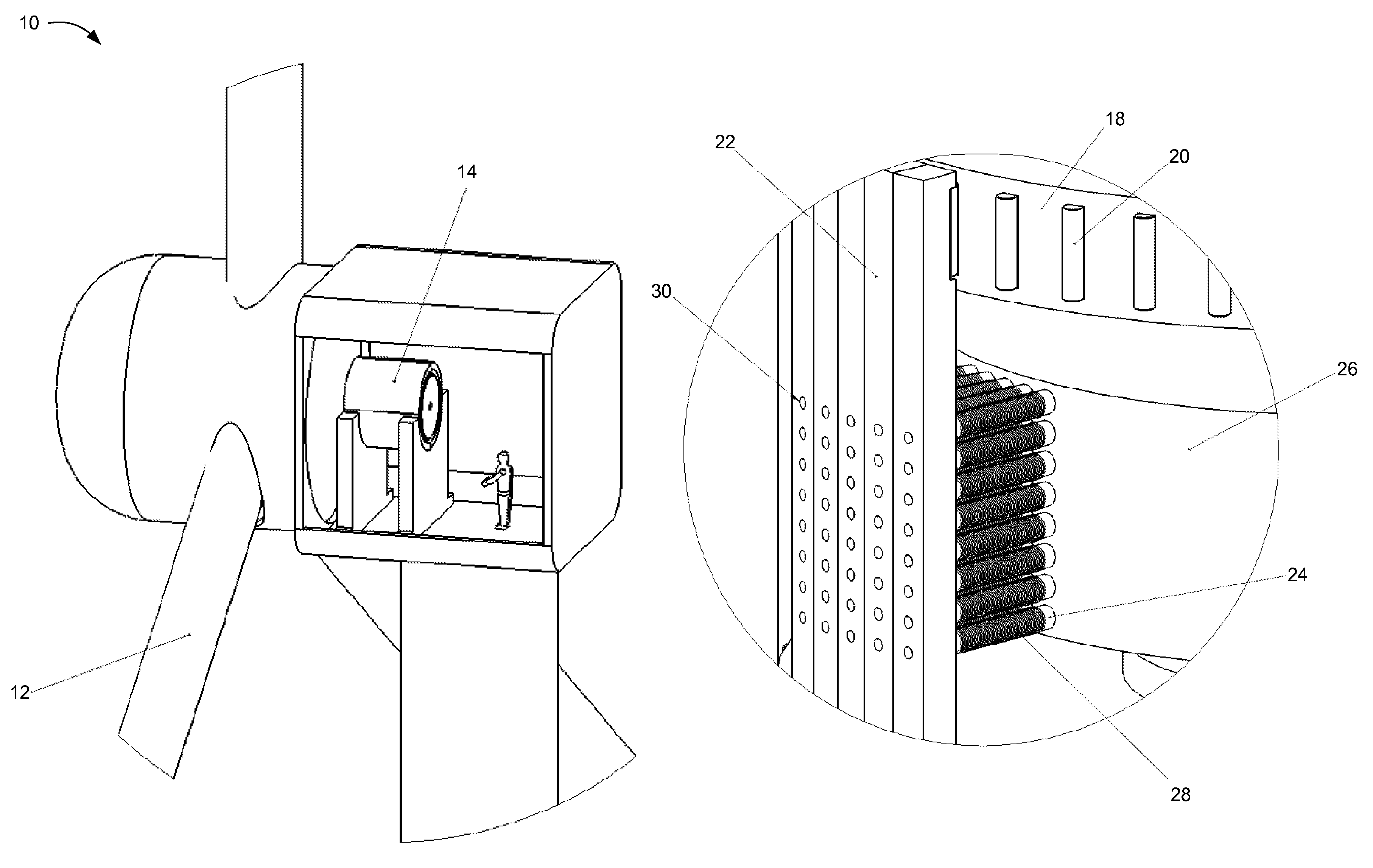
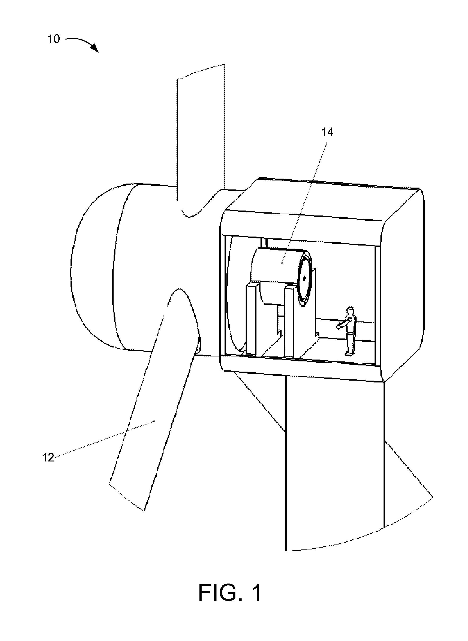
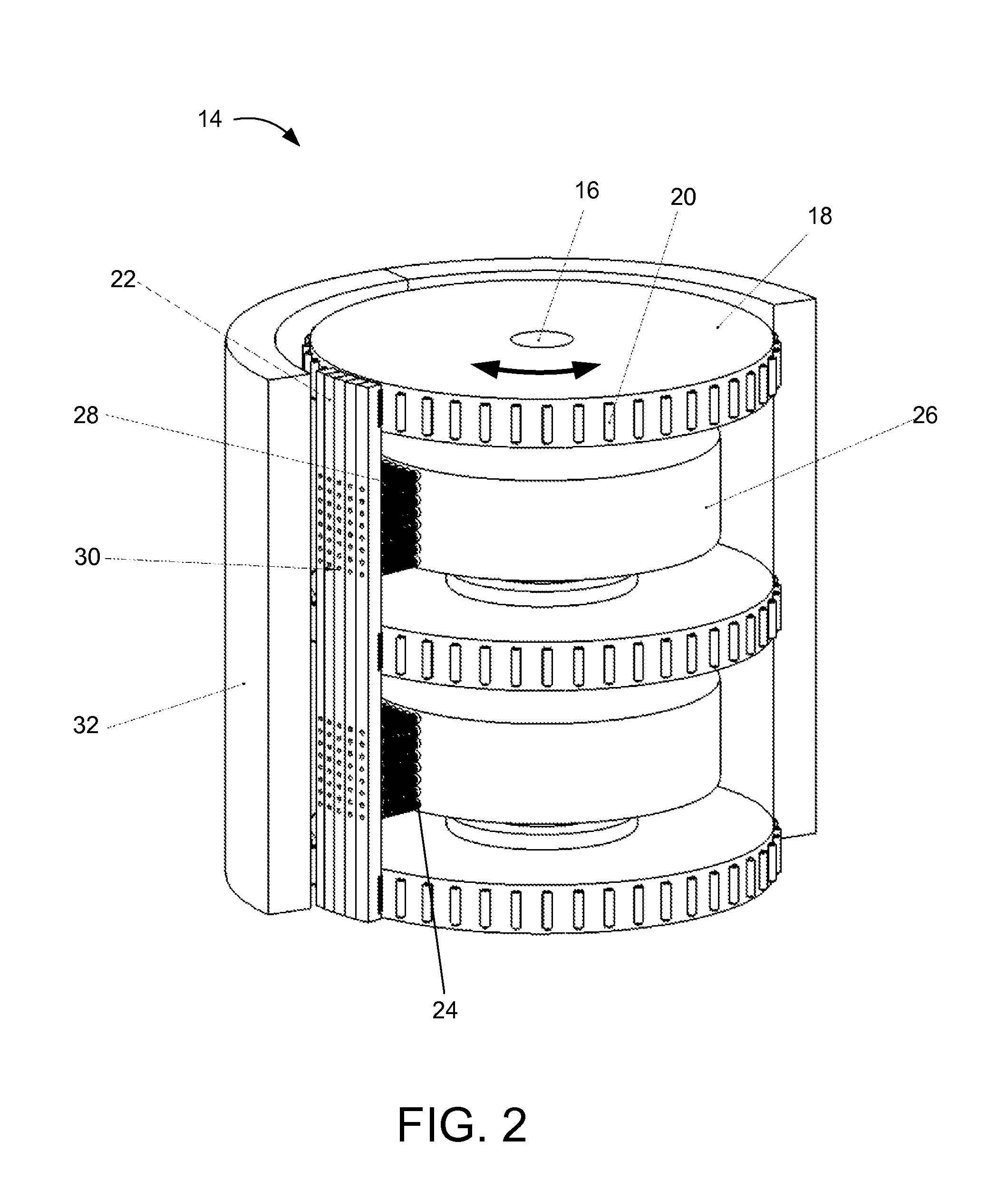
It will be readily understood that the components of the embodiments as generally described herein and illustrated in the appended figures could be arranged and designed in a wide variety of different configurations. Thus, the following more detailed description of various embodiments, as represented in the figures, is not intended to limit the scope of the present disclosure, but is merely representative of various embodiments. While the various aspects of the embodiments are presented in drawings, the drawings are not necessarily drawn to scale unless specifically indicated.

The present invention may be embodied in other specific forms without departing from its spirit or essential characteristics. The described embodiments are to be considered in all respects only as illustrative and not restrictive. The scope of the invention is, therefore, indicated by the appended claims rather than by this detailed description. All changes which come within the meaning and range of equivalency...


PUM


Abstract

A method and device for using magnetostriction to generate electricity from fluid motion. The device includes a first structural component, an outer housing, and a strain structure. The outer housing substantially circumscribes the first structural component and at least partially defines an annular space between the first structural component and the outer housing. The strain structure is coupled within the annular space between the first structural component and the outer housing. The strain structure experiences a change in physical strain imposed by a bearing in response to a relative movement between the bearing and the strain structure. The strain structure includes a magnetostrictive material to generate a magnetic field in response to the change in the physical strain.

Description

BACKGROUNDEmbodiments of the invention described herein relate to a method and device for producing electricity by conversion of the mechanical energy of wind or other moving fluids.Wind power, one of the most promising sources of renewable energy, is starting to be adopted more and more globally. Conventional wind power is based on wind turbines. Conventional wind turbines are rotating machines that convert the kinetic energy in wind into mechanical energy. Wind turbines can be separated into two types based by the axis around which the turbine rotates. Most turbines rotate around a horizontal axis, but some designs have been proposed where the turbine rotates around a vertical axis. Globally, the installed wind capacity was in excess of 120 GW by the end of 2008.Horizontal axis wind turbines used in commercial wind farms are usually of a three-bladed design. Computer controlled motors orient the blades to face the wind direction. A gear box is commonly used to step up the speed of...

Claims


Application Information

Patent Timeline
Patent Type & Authority Patents(United States)
IPC IPC(8): F03D9/00
CPCF03D11/0008H02N2/18H01L41/125F05B2220/7066F05B2240/40F05B2240/511F05B2280/5008Y02B10/30Y02E10/722Y02E10/725F05C2251/12F03D80/70Y02E10/72H10N35/101
Inventor NAIR, BALAKRISHNANNACHLAS, JESSE ALAN
Owner OSCILLA POWER
Why Eureka
Try Eureka