Radio frequency IC tag and method for manufacturing the same
- Summary
- Abstract
- Description
- Claims
- Application Information
AI Technical Summary
Benefits of technology
Problems solved by technology
Method used
Image
Examples
first embodiment
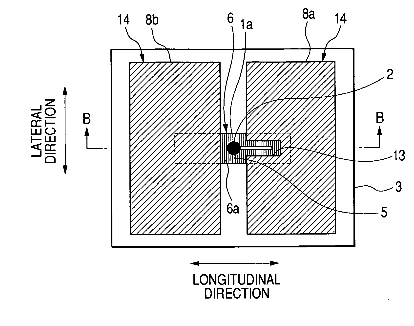
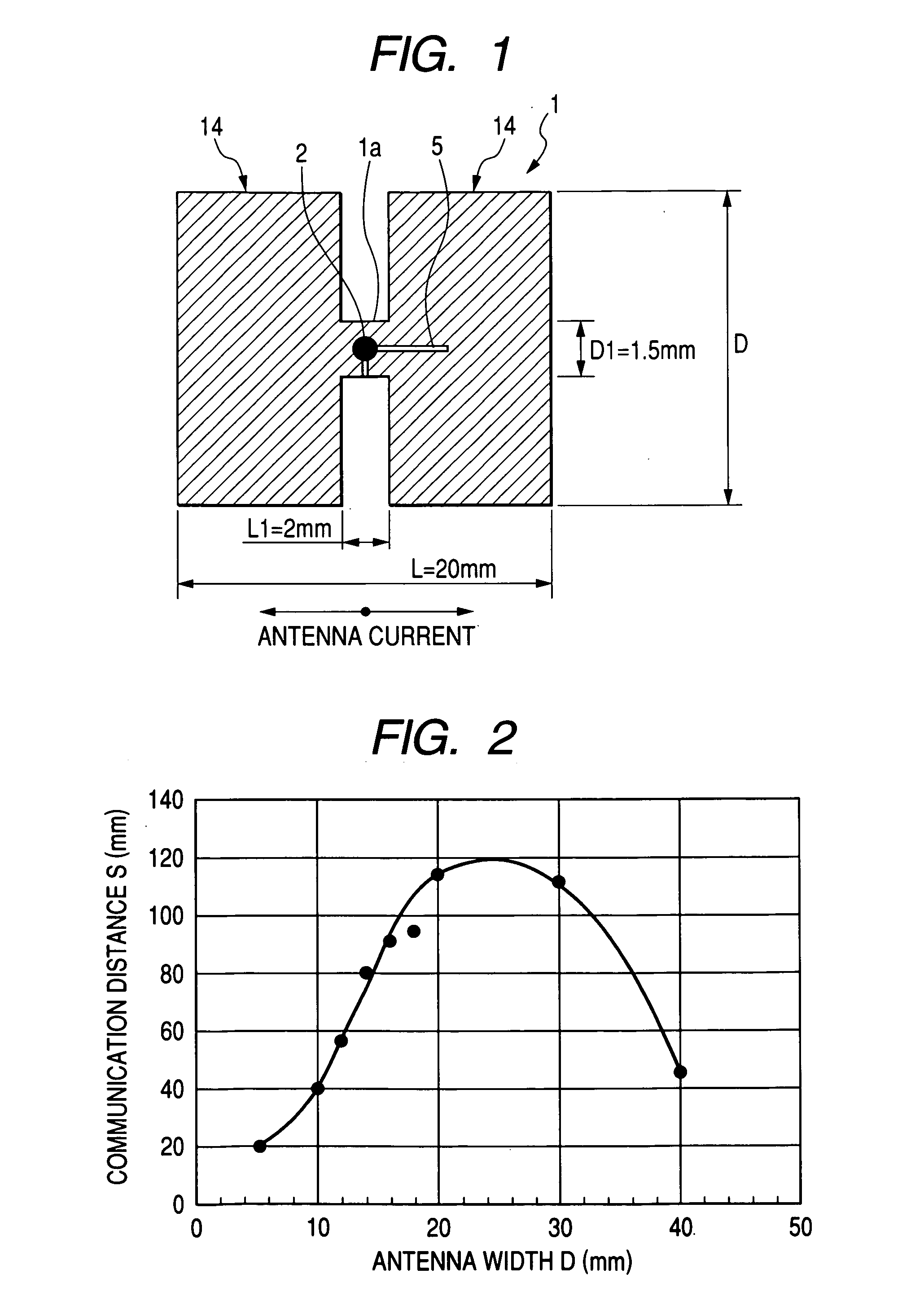
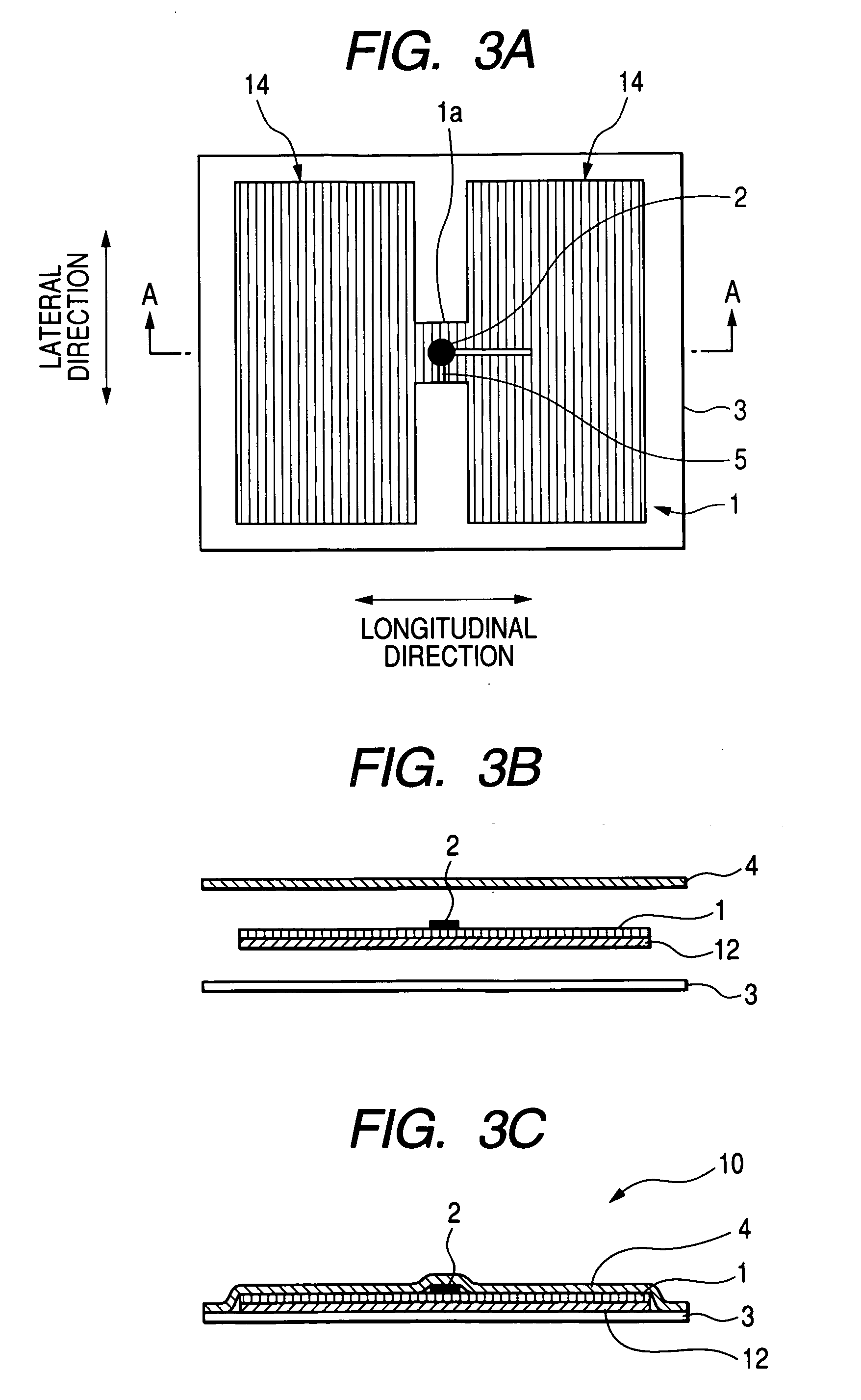
[0027]FIG. 1 is a plan view illustrating an H type antenna used in a radio frequency IC tag according to a first embodiment of the present invention. As shown in FIG. 1, an H type antenna 1 used in the radio frequency IC tag has a so-called H shape in which the antenna width D1 is narrowed in the central part of the antenna forming a constriction 1a extending in a direction of a length L1 while the antenna width D is widened at both side parts (peripheral radiation parts) 14 of the antenna 1 extending in the direction of the length L. In addition, an IC chip 2 is mounted on the central part of the H type antenna 1. The H type antenna 1 functions as a strip antenna. The H type antenna 1 takes preventive measures against electrostatic discharge damage, and performs impedance matching. Therefore, a consecutive key-shaped (or L-shaped) slit 5 is formed in the central part equipped with the IC chip 2 in such a manner that the IC chip 2 is placed across the slit 5, and the terminals of th...
second embodiment
[0049]FIG. 5 is a plan view illustrating an O type (dumbbell or oval type) antenna used in a radio frequency IC tag according to a second embodiment of the present invention. As shown in FIG. 5, an O type antenna 9 having a generally circular or oval shape has a configuration in which the central part 9a between two pieces of semicircular metal foil 15 having a radius of R is connected with rectangular metal foil having a width of D2. The rectangular metal foil part is equipped with the IC chip 2 to form a radio frequency IC tag. When an antenna current flows from the IC chip 2 of the O type antenna 9 having such a shape toward a direction indicated by an arrow in FIG. 5, the maximum current flows in the central part 9a (the part equipped with the IC chip 2 which forms a power-feeding part), and the antenna current then flows toward semicircular parts 15 at both sides, which act as radiation parts. As a result, the electromagnetic energy of the semicircular parts 15 at both sides su...
third embodiment
[0050] What will be described in this embodiment are some variations of radio frequency IC tags in which the shapes of the H type antenna and of the O type antenna described above are changed. In the embodiments described above, the width of the central part of an antenna extending in the longitudinal direction is narrowed to form an H-shaped or O-shaped antenna, and the radio frequency IC tag is equipped with the IC chip in the central part of the antenna. On the contrary, in a radio frequency IC tag according to a third embodiment, a position at which the IC chip is mounted (that is, a constriction) is moved from the central part of the antenna to a desired position so as to form an H type antenna, or an O type antenna, having a changed shape. In another case, the right and left shapes of an H type antenna or of an O type antenna, or the top and bottom shapes of an H type antenna or of an O type antenna, are made asymmetric so as to form the H type antenna, or the O type antenna, ...
PUM
| Property | Measurement | Unit |
|---|---|---|
| Current | aaaaa | aaaaa |
| Shape | aaaaa | aaaaa |
| Width | aaaaa | aaaaa |
Abstract
Description
Claims
Application Information
 - R&D
- Intellectual Property
- Life Sciences
- Materials
- Tech Scout
- Unparalleled Data Quality
- Higher Quality Content
- 60% Fewer Hallucinations
Browse by: Latest US Patents, China's latest patents, Technical Efficacy Thesaurus, Application Domain, Technology Topic, Popular Technical Reports.
© 2025 PatSnap. All rights reserved.Legal|Privacy policy|Modern Slavery Act Transparency Statement|Sitemap|About US| Contact US: help@patsnap.com


