Ergonomic pointing device

Active Publication Date: 2005-12-15
HUMANSCALE CORP
View PDF52 Cites 35 Cited by
  • Summary
  • Abstract
  • Description
  • Claims
  • Application Information

AI Technical Summary

Benefits of technology

[0036] The front region may include buttons on which to place the second and third digits. The buttons are desirably aligned with the phalanges of the second and third digits, respectively. In this way, the digits can operate the buttons efficiently by pressing downward in a substantially neutral position without awkward or strained movements (i.e., abduction or adduction).
[0037] In some embodiments, the housing includes an inner side surface on which to place the thumb, and an outer side surface on which to place the fifth digit and possibly the fourth digit. The inner side surface includes an upper region with an inverted surface portion to face downwardly toward the distal phalange of the thumb. The outer s

Problems solved by technology

The problem with the traditional method for a human interacting with their personal computer is that the human body is not suited to sitting for hours at a time, particularly while typing, pointing, clicking, and staring at an illuminated screen.
This combination is further frustrated in that it can lead to muscle strain, fatigue and stress.
Even at home, but especially in a more stressful environment like an office, users may force their bodies into rigid positions that result in fatigue and muscle strain.
However, such prior art mice force the hand, wrist, and forearm to be twisted 80 to 90 degrees out of their natural and relaxed positions, and require constant muscular force to be applied to the hand, wrist, and forearm to maintain their positions.
The total effort and discomfort may not seem great at first, but when these mice are used over a prolonged and continuous period of time, users may get diseases associated with the use of the computer mouse (e.g. tendinitis, bursitis, and carpal tunnel syndrome) and experience fatigue, discomfort, and even pain in the hand and wrist.
However, standardization of function assignment presents a problem when a mouse is used by persons of different handedness.
This operation may be awkward and is confusing if the user also operates a computer with a left-handed mouse.
While this is useful in maintaining the desired relationship between the finger used to initiate the function for right-handed and left-handed mice,

Method used


Image

  • Ergonomic pointing device
  • Ergonomic pointing device
  • Ergonomic pointing device

Examples


Embodiment Construction

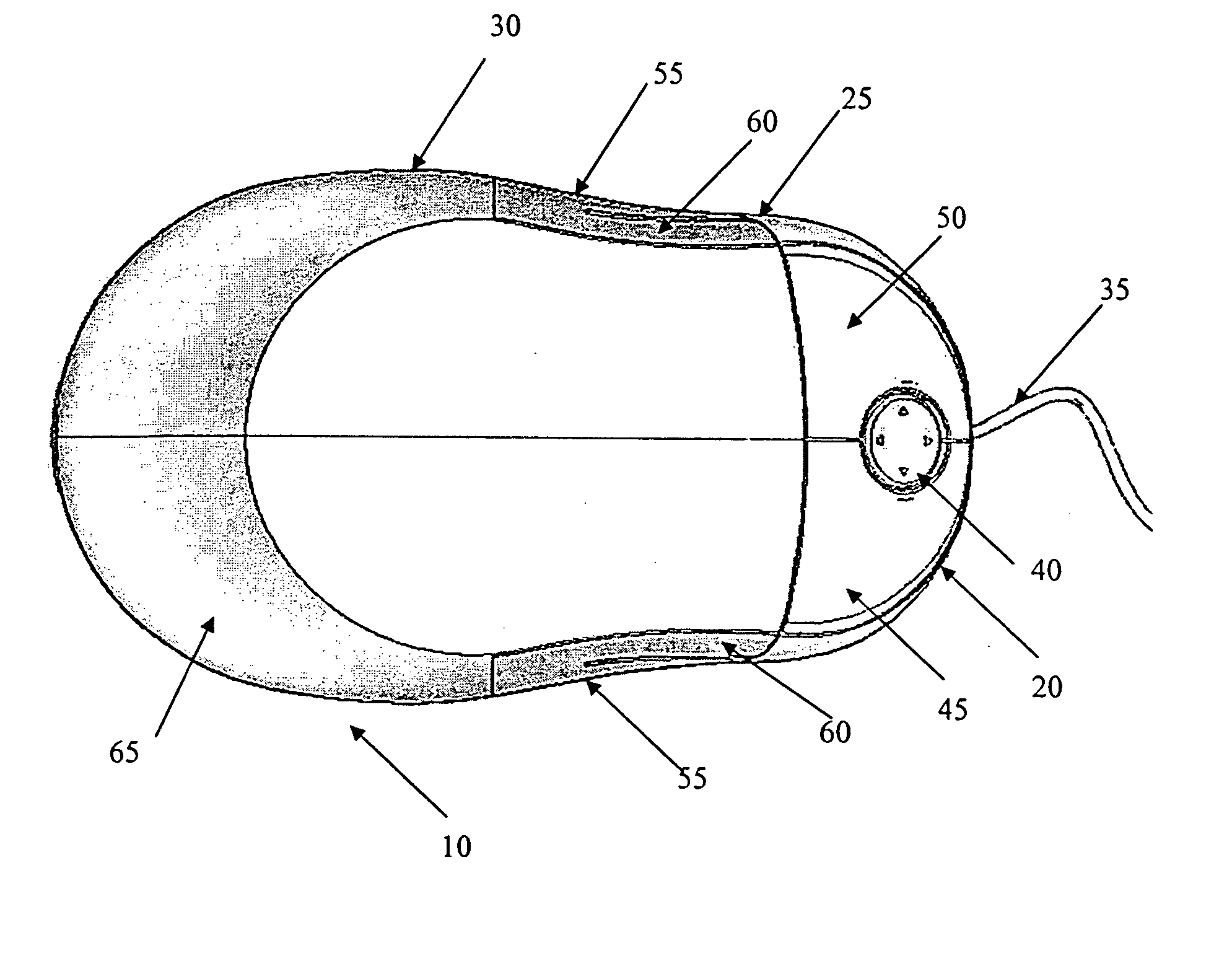
[0078] Referring now to the several views of the drawings, there is depicted a data input device in accordance with the present invention.

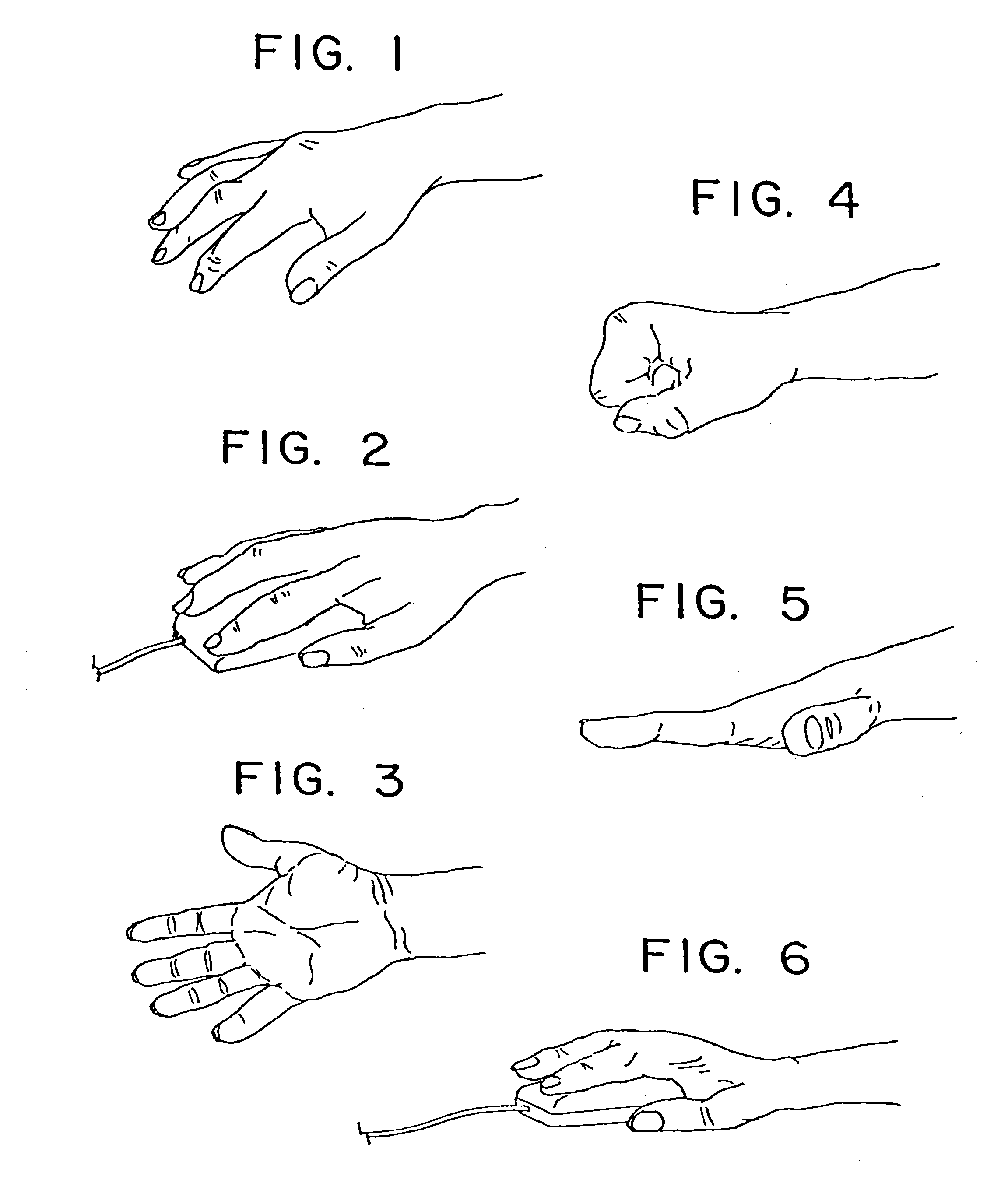
[0079]FIG. 1 depicts the hand in pronation, the forced position which is used with an ordinary mouse (FIG. 2). FIG. 3 is the hand in supination, the opposite of the position shown in FIGS. 1 and 2. FIG. 4 shows the band in flexion, with effort of the flexor muscle groups. FIG. 5 depicts effort of the extensor muscle groups when the hand is in extension. FIG. 6 depicts use of an ordinary mouse with the hand extended.

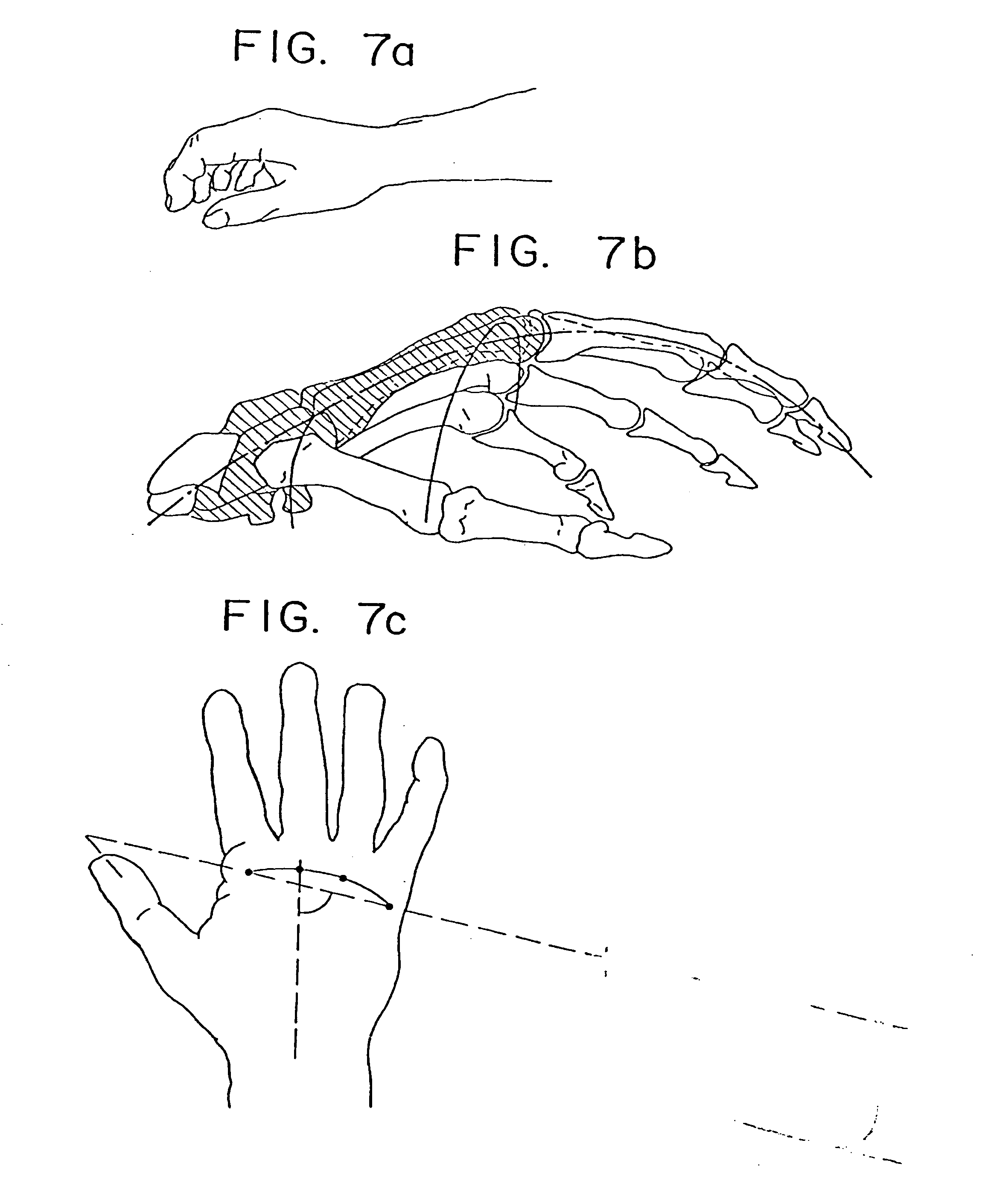
[0080]FIG. 7a depicts the hand in the “physiological position” or “position of function.” The “position of function” is discussed in The Hand, (1985) Vol. II, Chapter 53, pp. 497-501, published by W. B. Saunders Company, the disclosure of which is hereby incorporated by reference as though fully set forth herein. The skeleton of the hand has a transverse and longitudinal (i.e., double) concavity, which gives it the shape of a cup with...


PUM


Abstract

An input device for a computer is described that positions the user's hand in a more ergonomically desirable position, i.e., at an angle of about 45° to the work surface. In preferred embodiments, the input device accommodates either a user's left or right hand, and in either case, positions the hand in an ergonomically desirable position. In another embodiment, the length of the input device of the present invention is adjusted for the size of the user's hand. In further embodiments, the input device of the present invention provides a palm rest. Other desirable features included in preferred embodiments include lateral buttons that are positioned one above the other.

Description

FIELD OF THE INVENTION [0001] The present invention relates to data input devices, and more particularly to a data input device that positions the user's hand in an ergonomically appropriate position to reduce the risk of repetitive motion injury. Further, the data input device is adapted to be used in both a right-hand and left-hand configuration. BACKGROUND OF THE INVENTION [0002] The torrent of technological innovation over the last 15 years has done little to change the way most people usually interact with their personal computers, which is generally by sitting in front of a keyboard, mouse and monitor. [0003] The problem with the traditional method for a human interacting with their personal computer is that the human body is not suited to sitting for hours at a time, particularly while typing, pointing, clicking, and staring at an illuminated screen. This combination is further frustrated in that it can lead to muscle strain, fatigue and stress. Still, experts in ergonomics s...

Claims


Application Information

Patent Timeline
IPC IPC(8): A61K9/00G06F3/033G09G5/00
CPCG06F3/03543G06F2203/0333G06F2203/0332
Inventor SAEZ, MANUELTSVETANOV, LACHEZARHEER, MAXIMO DIAZPULEIO, JONATHAN
Owner HUMANSCALE CORP
Why Eureka
Try Eureka