Imaging lens

a lightweight, imaging lens technology, applied in the field of imaging lenses, can solve the problem that the back focus of the imaging lens must be extended to a certain degree, and achieve the effect of substantial aperture efficiency and satisfactory correction of distortion

Active Publication Date: 2005-12-15
MAXELL FINETECH
View PDF5 Cites 19 Cited by
  • Summary
  • Abstract
  • Description
  • Claims
  • Application Information

AI Technical Summary

Benefits of technology

[0025] Next, when the imaging surface is a CCD, CMOS, or the like, a limit is placed on the ray angle incorporated into each pixel in order to ensure substantial aperture efficiency. To mitigate this phenomenon, it is preferred that the exit pupil be lengthened and that the maximum exit angle of the principal ray be corrected to 30 degrees or less. Shading can thereby be prevented from occurring in the periphery of the image surface. Distortion can also be satisfactorily corrected by appropriately designing the aspherical shape.

Problems solved by technology

A limitation therefore exists in that the back focus of the imaging lens must be lengthened to a certain degree.

Method used


Image

  • Imaging lens
  • Imaging lens
  • Imaging lens

Examples


example 1

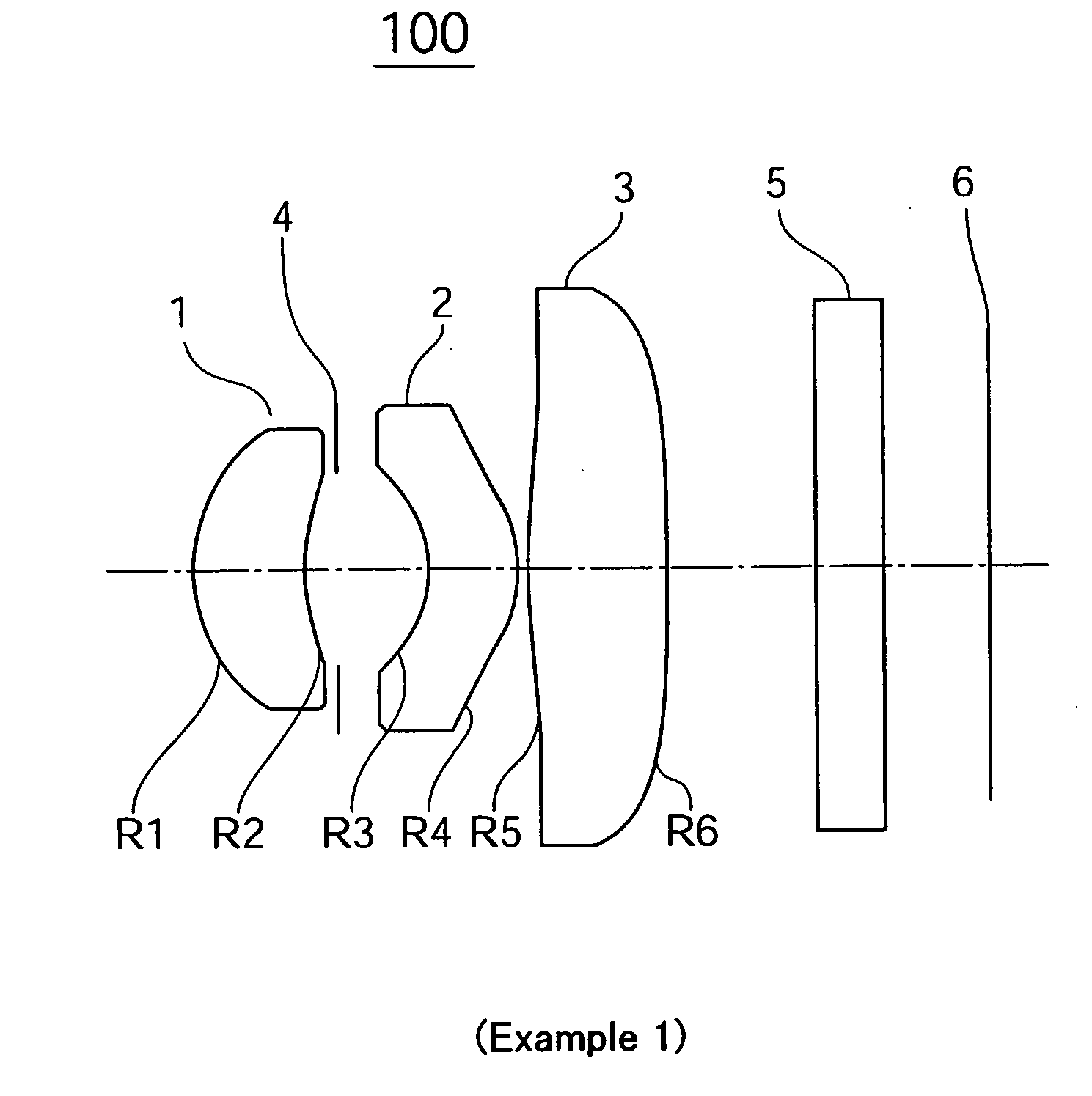
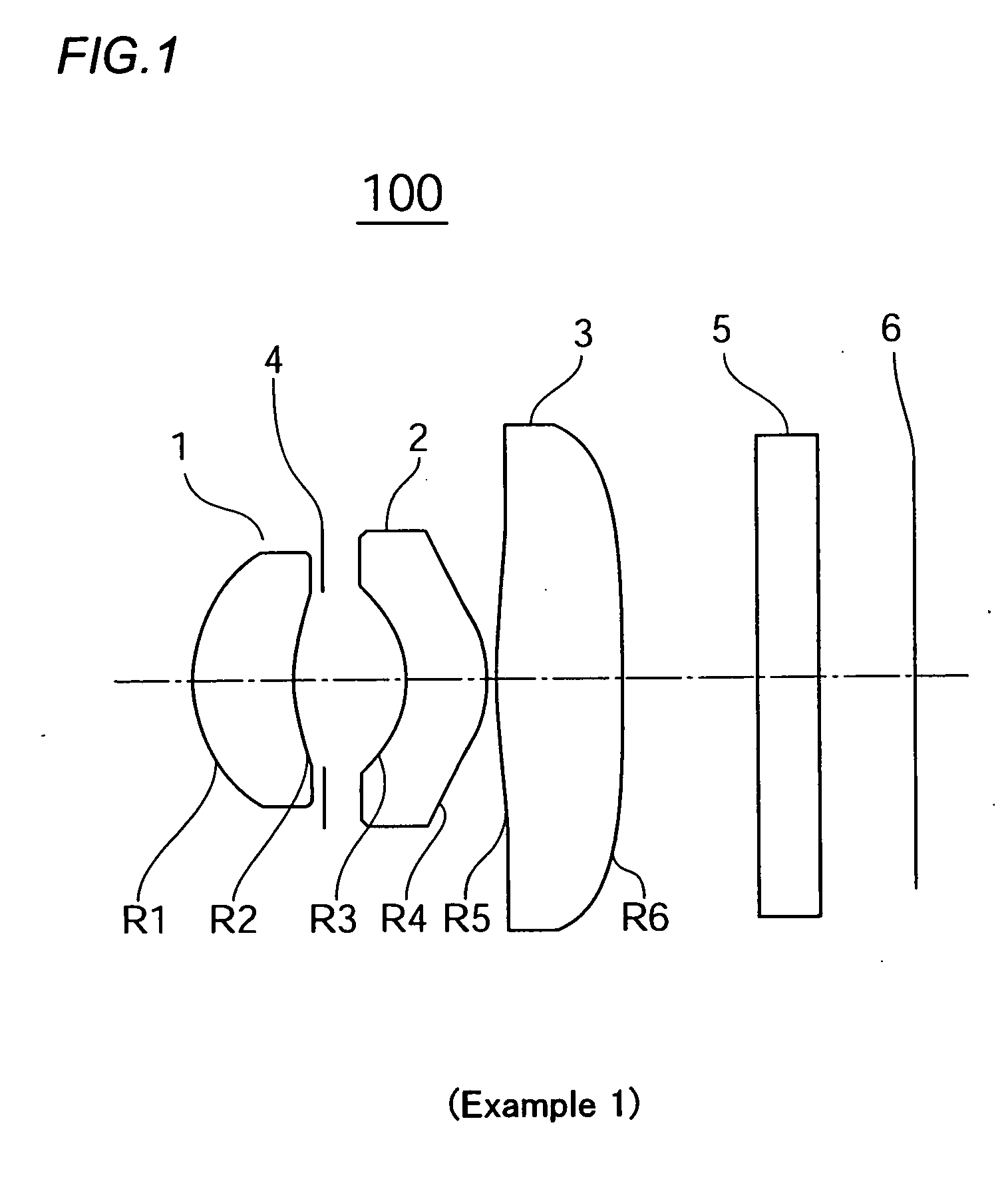
[0041] An imaging lens according to Example 1 in which the first invention of the present application is applied is depicted in FIG. 1. An imaging lens 100 of the present example has, arranged in sequence from an object side towards an imaging surface 6, a first lens 1 whose meniscus has a positive power and whose convex surface faces the object side; a second lens 2 whose meniscus has a negative power and whose concave surface faces the object side, positioned subsequently via an aperture 4; and a third lens 3 having a positive power; and the second and third lenses function as correction lenses. In the present example, all of the lens surfaces on both sides of lenses 1, 2, and 3 are aspherical. In the present example, a cover glass 5 is mounted between the second lens surface R6 of the third lens 3 and the imaging surface 6.

[0042] In the third lens 3, an aspherical inflection point is provided in the location of substantially 50% of the aperture diameter in the first lens surface...

example 2

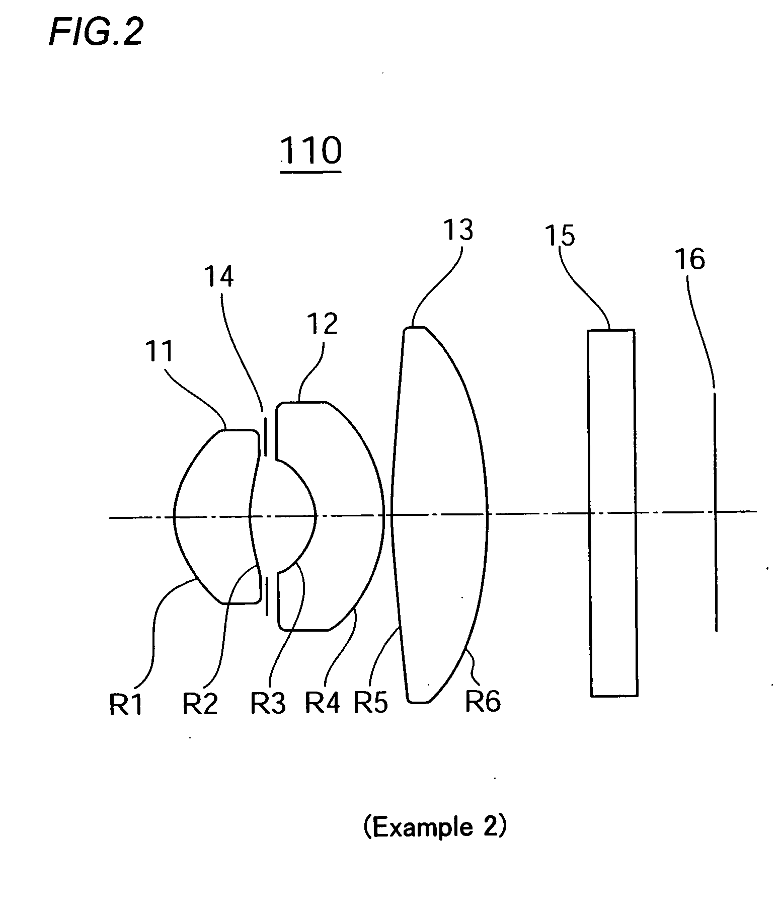
[0053]FIG. 2 is a structural diagram of an imaging lens according to Example 2 in which the first invention of the present application is applied. In an imaging lens 110 of the present example, a first lens 11 with a positive meniscus whose convex surface faces an object side, a second lens 12 with a negative meniscus whose concave surface faces the object side, positioned via an aperture 14, and a third lens 13 that is a biconvex lens are arranged in sequence from the object side towards an imaging surface 16. An aspherical inflection point is provided in the location of substantially 48% of the lens aperture diameter in the first lens surface R5 of the third lens 13 on the object side. The second lens surface R6 thereof on the image side is formed as an extension of the convex surface. Forming the lens surface of the third lens 13 in this manner allows the maximum exit angle of the principal ray to be 23.5 degrees with respect to the total angle of view of 63 degrees. The lens sur...

example 3

[0061] An imaging lens according to Example 3 in which the first invention of the present application is applied is shown in FIG. 5. An imaging lens 120 of the present example has, arranged in sequence from an object side towards an imaging surface 26, a first lens 21 whose meniscus has a positive power and whose convex surface faces the object side; a second lens 22 whose meniscus has a negative power and whose concave surface faces the object side, positioned subsequently via an aperture 24; and a third lens 23 having a negative power; and the second and third lenses function as correction lenses. A cover glass 25 is mounted between the third lens 23 and the imaging surface 26. In the third lens 23, the second lens surface R6 on the side of the imaging surface is formed so that the annular zone of the lens periphery forms a convex surface towards the imaging surface side, and the maximum exit angle of the principal ray is adjusted to 24 degrees or less.

[0062] In the present examp...


PUM


Abstract

An imaging lens (100) comprising, arranged sequentially from the object side, a positive-meniscus first lens (1) with its convex plane facing the object side, a negative-power-meniscus second lens (2), and a positive-power third lens (3), the second and third lenses (2, 3) functioning as correction lenses. The first lens (1) has a strong power, and both the second and third lenses (2, 3) are aspherical on opposite planes. When the synthetic focal distance of the imaging lens is f, the focal distance of the first lens f1, the distance from the incident surface on the object side to the imaging surface of the first lens (1) Σd, and the Abbe number of the second lens {square root}d2, the following conditional expressions are satisfied. 0.50<f1/f<1.5 (1) 0.50<Σd/f<1.5 (2) 50>{square root}d2 (3). Accordingly, a small, low-cost imaging lens capable of high-quality imaging can be realized.

Description

TECHNICAL FIELD [0001] The present invention relates to a small, lightweight imaging lens used in an automobile-mounted camera, a surveillance camera, a digital camera, a camera installed in a mobile telephone, or the like that uses a CCD, CMOS, or other photosensor. BACKGROUND ART [0002] It is desired that an imaging lens installed in surveillance cameras, digital cameras, and other devices that use CCD, CMOS, or other photosensors be provided with the ability to faithfully reproduce the subject. CCDs themselves or CCD cameras have also been made smaller in recent years, which has been accompanied by an inevitable increase in the demand for miniaturization and compact design of the imaging lenses incorporated therein. CCD and other photosensors have also been provided with high resolution on the order of millions of pixels in contrast with CCD miniaturization. It has inevitably become necessary for the imaging lenses used in cameras having such sensors to also be capable of demonst...

Claims


Application Information

Patent Timeline
Patent Type & Authority Applications(United States)
IPC IPC(8): G02B9/16G02B13/00G02B13/18
CPCG02B9/16G02B13/18G02B13/0035G02B13/00G02B3/0087G02B3/04G02B2003/0093
Inventor KUBOTA, YOJIMATSUI, TOSHIO
Owner MAXELL FINETECH
Why Eureka
Try Eureka