Microstructure designs for optimizing mixing and pressure drop

a micro-structure and pressure drop technology, applied in the direction of transportation and packaging, chemical/physical/physicochemical processes, other chemical processes, etc., can solve the problems of large diffusion limitation of reaction processes, difficult to increase the interfacial area between two fluids or to mix at very small scales without external stirring or mechanical action, etc., to achieve the effect of increasing the mixing efficiency

Active Publication Date: 2005-12-15
CORNING INC
View PDF24 Cites 31 Cited by
  • Summary
  • Abstract
  • Description
  • Claims
  • Application Information

AI Technical Summary

Benefits of technology

[0018] One embodiment of the present invention relates to a mixer apparatus having at least one injection zone of a continuous flow path where a plurality of fluids make initial contact and at least one mixer element in the flow path, the at least one mixer element efficiently mixing the fluids through the path. Each one of the mixer elements includes a channel segment, a chamber disposed at ends of the channel segment and each chamber further includes at least one obstacle.
[0021] Another embodiment of the present invention relates to inner dimensions of the chamber being reduced in the presence of the at least one obstacle and wherein increased dimensions of said obstacle increase the mixing efficiency.

Problems solved by technology

Increasing the interfacial area between two fluids or mixing at very small scales without external stirring or mechanical action is very difficult because of the low Reynolds numbers involved, especially for nearly two dimensional geometries.
Therefore, reaction processes are largely diffusion limited.
The second approach utilizing three-dimensional or chaotropic flows has several drawbacks, one being the aspect ratio between the height and width of the channel, another being costly technology, and yet another being that it is useful for liquids only and not gas-liquid systems.
All the above devices have great difficulty achieving low pressure drop.
This is generally thought to be caused by the prior art designs' attempts at reducing dimensions to enhance mixing efficiency thereby dramatically increasing the pressure drop, which is a penalty.

Method used


Image

  • Microstructure designs for optimizing mixing and pressure drop
  • Microstructure designs for optimizing mixing and pressure drop
  • Microstructure designs for optimizing mixing and pressure drop

Examples


Embodiment Construction

[0042] Reference will now be made in detail to the present preferred embodiments of the invention, examples of which are illustrated in the accompanying drawings. Wherever possible, the same reference numbers will be used throughout the drawings to refer to the same or like parts.

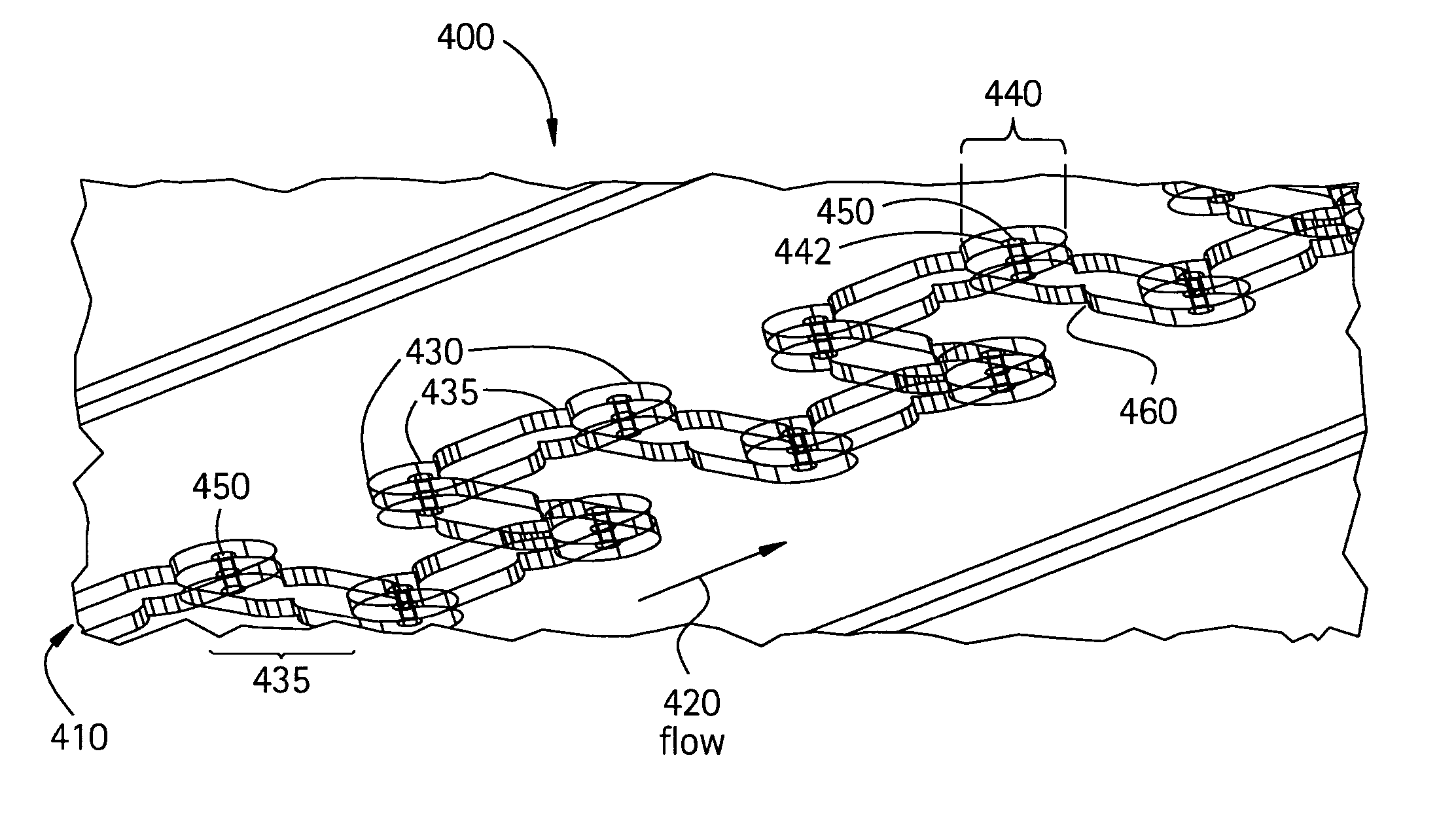
[0043] Referring to FIG. 4, a three-dimensional view of mixer 400 is shown in accordance with a preferred embodiment of the present invention to include an injection zone 410 where two or more fluids or reactants (not shown) would make initial contact and flow upstream as indicated at arrow 420. Forming a somewhat snake-like shape, a series of mixer elements 430 are shown to include: 1.) fairly rectangular channel segments 435 (with slightly rounded corners); and 2.) a chamber 440 at each end of the channel segment, with an obstacle 450 positioned inside of the chamber in accordance with a preferred embodiment of the present invention of the mixer 400. In accordance with another aspect of the preferred emb...


PUM


Abstract

A class of designs is provided for a mixer in micro reactors where the design principle includes at least one injection zone in a continuous flow path where at least two fluids achieve initial upstream contact and an effective mixing zone (i.e. adequate flow of fluids and optimal pressure drop) containing a series of mixer elements in the path. Each mixer element is preferably designed with a chamber at each end in which an obstacle is placed (thereby reducing the typical inner dimension of the chamber) and with optional restrictions in the channel segments. The obstacles are preferably cylindrical pillars but can have any geometry within a range of dimensions and may be in series or parallel along the flow path to provide the desired flow-rate, mixing and pressure-drop. The injection zone may have two or more interfaces and may include one or more cores to control fluids before mixing.

Description

FIELD OF THE INVENTION [0001] This invention relates generally to micro reactor systems and devices and more particularly to a class of designs for mixers used within micro reactor systems. BACKGROUND OF THE INVENTION [0002] Many multiphase fluidic applications require mixing or at least enhancement of interfacial area. In micro-fluidic systems, typical dimensions are below 1 mm and make the mixing and / or the agitation a first order issue. Indeed the typical flows often involved in these applications are creeping flows in which two initial miscible or non miscible fluids hardly mix by themselves (turbulence in fluid flows being commonly used for achieving mixing in large-scale fluid systems). Increasing the interfacial area between two fluids or mixing at very small scales without external stirring or mechanical action is very difficult because of the low Reynolds numbers involved, especially for nearly two dimensional geometries. Therefore, reaction processes are largely diffusion ...

Claims


Application Information

Patent Timeline
Patent Type & Authority Applications(United States)
IPC IPC(8): B01F5/04B01F5/06B01F13/00B01J19/00
CPCB01F5/0451B01F5/0453B01F5/046B01F2005/0636B01F5/0646B01F13/0059B01F2005/0621B01F5/061Y10S366/03B01F25/31324B01F25/3132B01F25/3131B01F25/4317B01F25/431B01F25/431971B01F25/433B01F33/30B01J19/00B01F25/00B01F25/40B01F33/00
Inventor WOEHL, PIERRETHEMONT, JEAN-PIERRENEDELEC, YANN P M
Owner CORNING INC
Why Eureka
Try Eureka