Transparent panel-form loudspeaker

a panel-form, loudspeaker technology, applied in the direction of transducer diaphragms, electromechanical transducers, diaphragm construction, etc., can solve the problems of large moving coil drivers, large weight, and limited application of panel-form loudspeakers

Inactive Publication Date: 2005-12-15
NEOSONICA TECH
View PDF2 Cites 19 Cited by
  • Summary
  • Abstract
  • Description
  • Claims
  • Application Information

AI Technical Summary

Benefits of technology

[0005] It is, therefore, a principal object of the present invention to provide a transparent panel-form loudspeaker which can produce a desired sound pressure level spectrum over a predetermined frequency range. The transparent panel-form loudspeaker includes a thin transparent sound radiation panel made of transparent materials, a preselected number of transducers situated at specific locations on the peripheral edge of the transparent sound radiation panel, a flexible suspension device used to support the peripheral edge of the transparent sound radiation panel, and a rigid frame used to carry the flexible suspension device. Sound quality and radiation efficiency of the transparent panel-form loudspeaker over a desired acoustic frequency range are dependent on values of particular parameters of the transparent panel-form loudspeaker, including the ratio of elastic modulus to density, the ratio of length to thickness of the transparent sound radiation panel, and locations of the transducers and supporting points of the flexible suspension device on the peripheral edge of the transparent sound radiation panel. A proper selection of the values of the parameters can produce the required achievable sound pressure level spectrum of the transparent panel-form loudspeaker for operation over a desired acoustic frequency range.

Problems solved by technology

The existence of such enclosure makes the loudspeaker cumbersome, weighty, having dead corner for sound radiation and etc.
The opaqueness, highly directional sound radiation, and geometry of the long radiating panel have limited the applications of this type of panel-form loudspeakers.
The design of such radiating panel, however, makes it so stiff that it requires a very large and cumbersome moving-coil driver to drive the panel and its overall efficiency from the viewpoint of electrical input is even less than the conventional loudspeakers.
Again the radiating panel of such loudspeaker is opaque and its applications are also limited.
Although the panel-form loudspeakers designed using this method can produce sound with wider frequency range than those using the other previously proposed methods, there are still some shortcomings that may limit the applications of this panel-form loudspeakers.
If the location of the transducer is merely determined using the first 20 to 25 resonant modes, it will be inevitable that some resonant modes in the middle and high frequency ranges will be over- or under-excited and this may lead to the formations of unfavourable peaks and pits in the sound pressure level spectrum of the panel-form loudspeaker.
For a vibrating panel, the sound waves radiated from the convex and concave regions on the panel surface are out-of-phase and can cause interference among them.
If the sound interference of the panel vibrating at a specific frequency is serious, the sound pressure level at that frequency will be significantly lowered and thus cause a pit in the sound pressure level spectrum.
The aforementioned difficulties, however, were not tackled by Azima et al.
Therefore, in view of the shortcomings existing in the panel-form loudspeakers, it is apparent that the previously proposed methods for the design of the existing panel-form loudspeakers can only find limited applications and are unsuitable to be used in the design of transparent panel-form loudspeakers.

Method used


Image

  • Transparent panel-form loudspeaker
  • Transparent panel-form loudspeaker
  • Transparent panel-form loudspeaker

Examples


Embodiment Construction

[0024] The theoretical background of the proposed method is illustrated as follows.

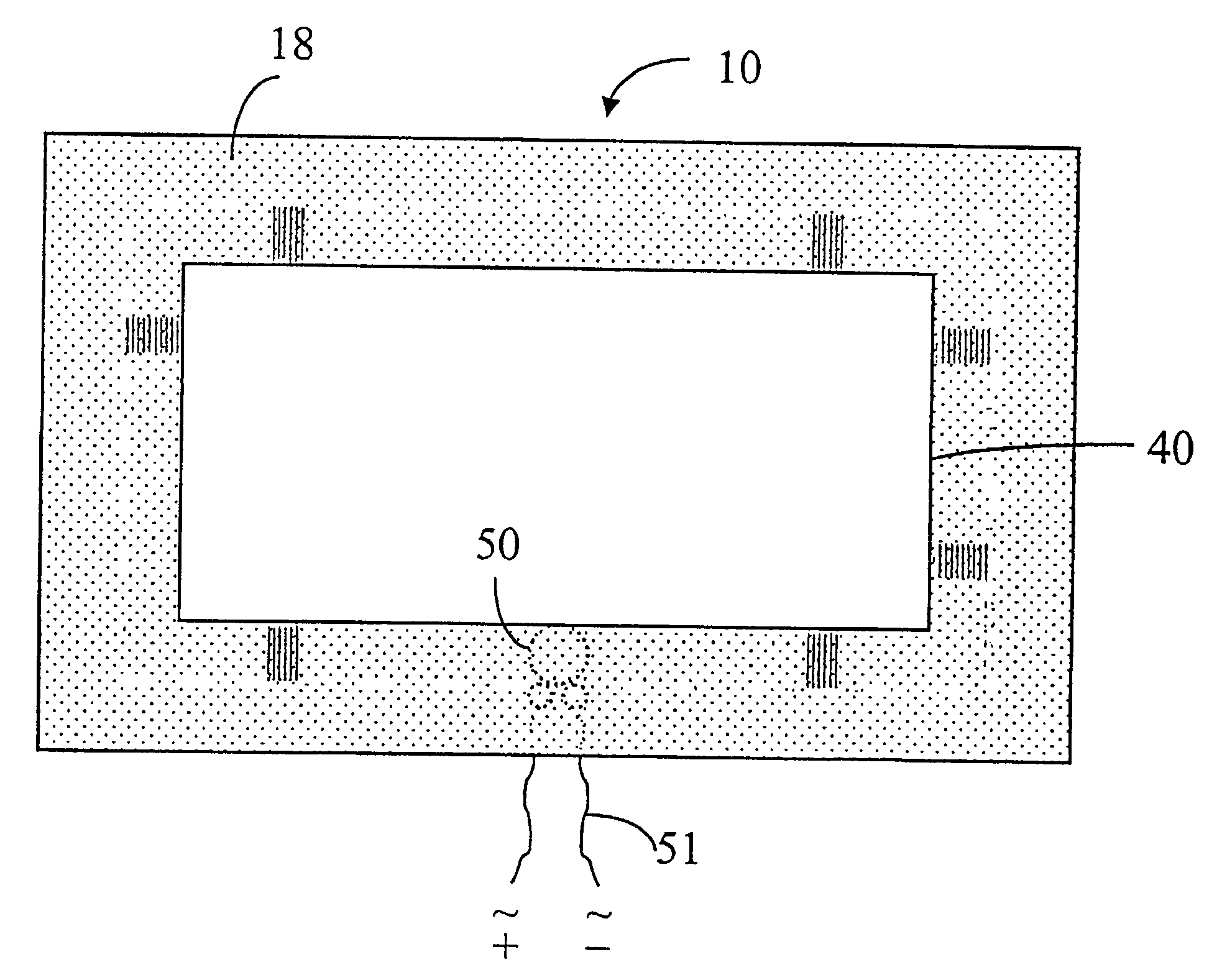
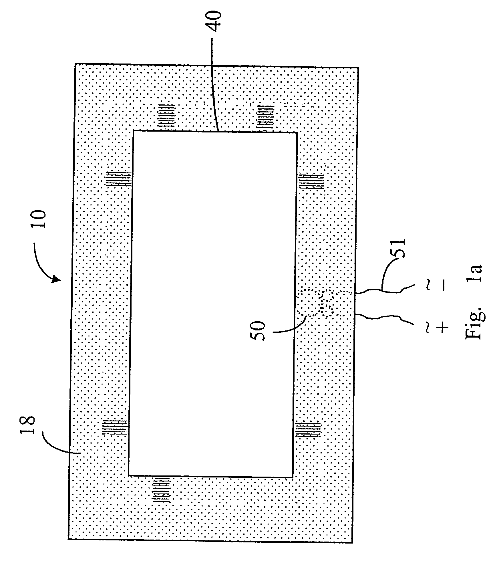
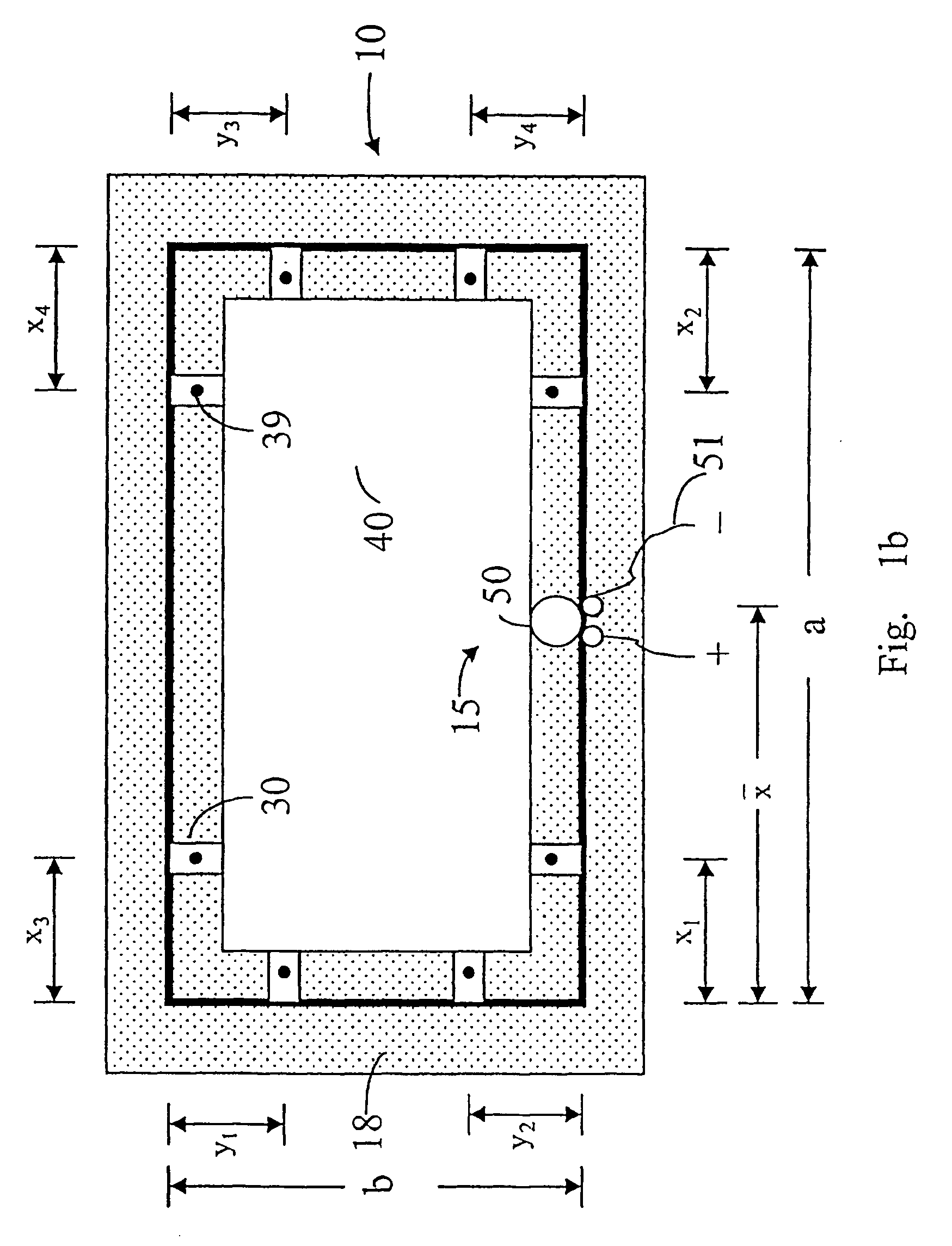
[0025] The method for the design of the present transparent panel-form loudspeaker is established on the basis of the effective modal parameters identification method which utilizes both the analyses of modal vibration and sound pressure level spectrum in identifying the beneficial modal parameters of the transparent panel radiator for sound radiation. In the effective modal parameters identification method, a vibrating transparent panel is modeled as a surface sound source which displaces air volume at the interface. For an infinitely extended or baffled plate under flexural vibration, the sound pressure radiated from the plate can be evaluated using Rayleigh's first integral. The on-axis far-field sound pressure P is then calculated using the following approximate expression P=-(ρω22⁢π)⁢∫s⁢W0⁡(x,y)⁢ⅇj⁡[β⁡(x,y)-kr]⁢dsr(1)

where ρ is air density, ω is vibrational angular frequency, k is wave number,...


PUM

PropertyMeasurementUnit
transparentaaaaaaaaaa
lengthaaaaaaaaaa
widthaaaaaaaaaa

Abstract

A transparent panel-form loudspeaker consists of a transparent sound radiation panel that can radiate sound with desired pressure level over a specific frequency range when subjected to the flexural vibration induced by a preselected number of transducers located at specific positions on the peripheral edge of the transparent sound radiation panel and a rigid frame carrying a flexible suspension device which supports the periphery of the transparent sound radiation panel. The transparent sound radiation panel is made of a kind of transparent materials with the ratio of elastic modulus to density in the range from 3 to 180 GPa / (g / cm3) and the ratio of length to thickness of the transparent sound radiation panel in the range from 80 to 600. The flexible suspension device supporting the periphery of the transparent sound radiation panel is used to modify the vibrational characteristics of the transparent sound radiation panel for an effective generation of the vibrational normal modes which are beneficial for sound radiation. The transducers are situated at predetermined locations on the peripheral edge of the transparent sound radiation panel so that relatively high radiation efficiency and more uniform spread of sound pressure level spectrum can be produced by the transparent sound radiation panel over a desired operative acoustic frequency range.

Description

CROSS REFERENCE TO RELATED APPLICATION [0001] This application is a division of U.S. patent application Ser. No. 09 / 989,604, filed Nov. 20, 2001, which is incorporated by reference as if fully set forth.FIELD OF THE INVENTION [0002] The invention relates to a panel-form loudspeaker utilizing a transparent sound radiation panel that can generate beneficial and effective vibrational normal modes for radiating sound with desired pressure level over a specific frequency range. BACKGROUND OF THE INVENTION [0003] The invention relates to a transparent panel-form loudspeaker utilizing a preselected number of transducers to excite a peripherally supported transparent panel to generate beneficial flexural vibrational mode shapes for radiating sound with desired pressure level over a specific frequency range. Conventional loudspeakers utilizing a cone-type membrane as a sound radiator have been widely used. The sound radiation of the conventional loudspeaker is achieved by attaching an electr...

Claims


Application Information

Patent Timeline
Patent Type & Authority Applications(United States)
IPC IPC(8): H04R9/02H04R1/02H04R7/04
CPCH04R7/045H04R2499/15Y10T29/49002Y10T29/49005Y10T29/4908
Inventor KAM, TAI-YAN
Owner NEOSONICA TECH
Why Eureka
Try Eureka