Lens driving mechanism and image pickup device

a driving mechanism and lens technology, applied in the field of new lenses, can solve the problems of affecting the reduction of power consumption, affecting the adjustment of the camera position, and affecting the adjustment of the power consumption,

Inactive Publication Date: 2005-12-15
SONY CORP
View PDF0 Cites 28 Cited by
  • Summary
  • Abstract
  • Description
  • Claims
  • Application Information

AI Technical Summary

Benefits of technology

[0035] In each of the embodiments, the link mechanism or each link mechanism may further include a first link linking the first lever and the electro-mechanical conversion element or its associated electro-mechanical conversion element and a second link linking the application point of the first lever or its associated first lever and the power point of the second lever or its associated second lever, and the first link and the power point of the first lever or each first link and the power point of each first lever, the second link and the application point of the first lever or each second link and the application point of

Problems solved by technology

Accordingly, although the camera movement is compensated for by shifting the correcting lens (unit) G3, the above-described method for correcting camera movement has several problems.
Therefore, during shooting, it is difficult to hold the correcting lens (unit) GR3 at a predetermined position when the coil c is not energized, thereby hindering a reduction in power consumption.
However, this method also has a problem in that, in order to stabilize the co

Method used


Image

  • Lens driving mechanism and image pickup device
  • Lens driving mechanism and image pickup device
  • Lens driving mechanism and image pickup device

Examples


Embodiment Construction

[0050] A lens driving mechanism and an image pickup device according to preferred embodiments of the present invention will hereunder be described with reference to the attached drawings.

[0051] A lens driving mechanism will be described.

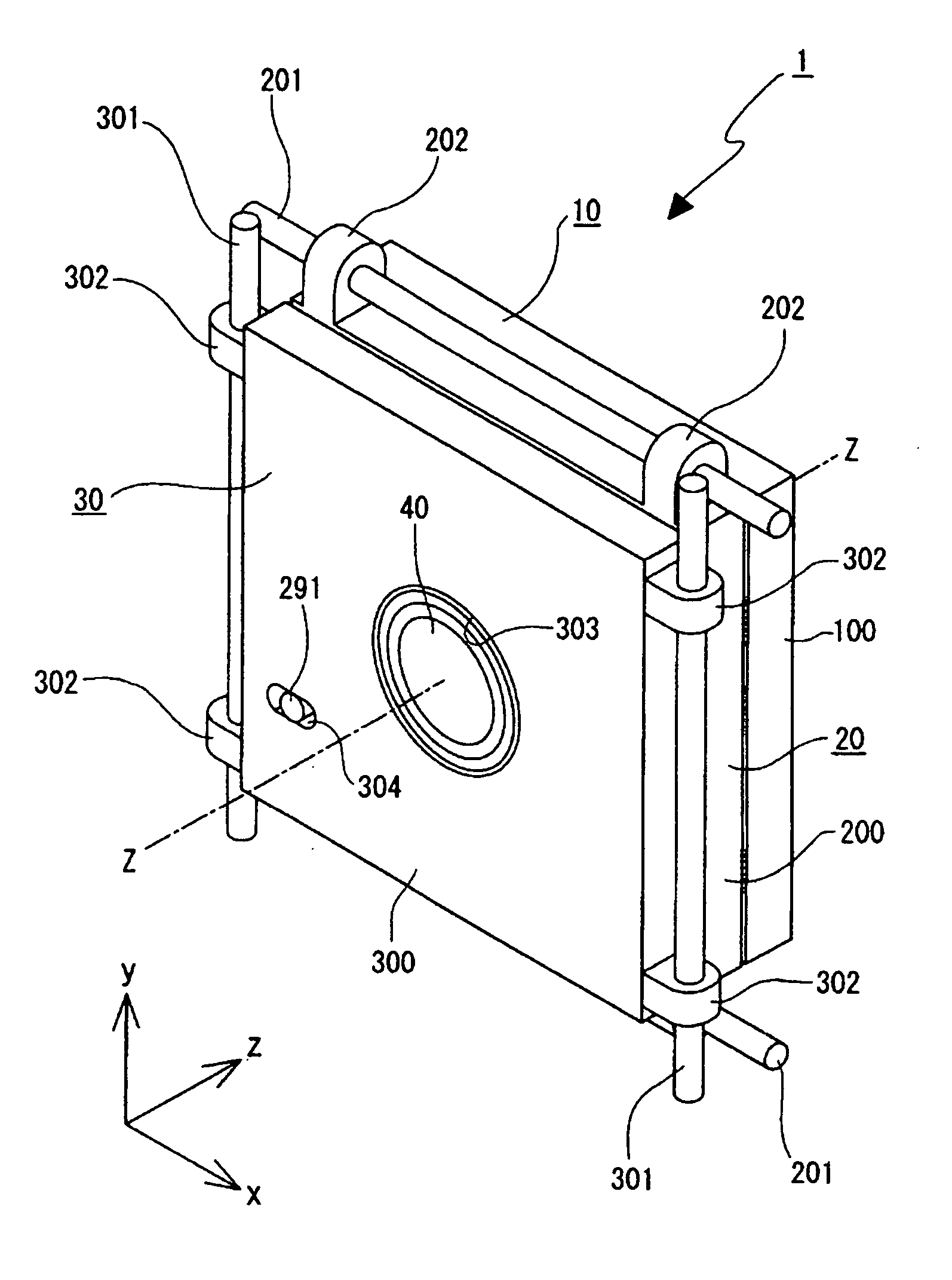
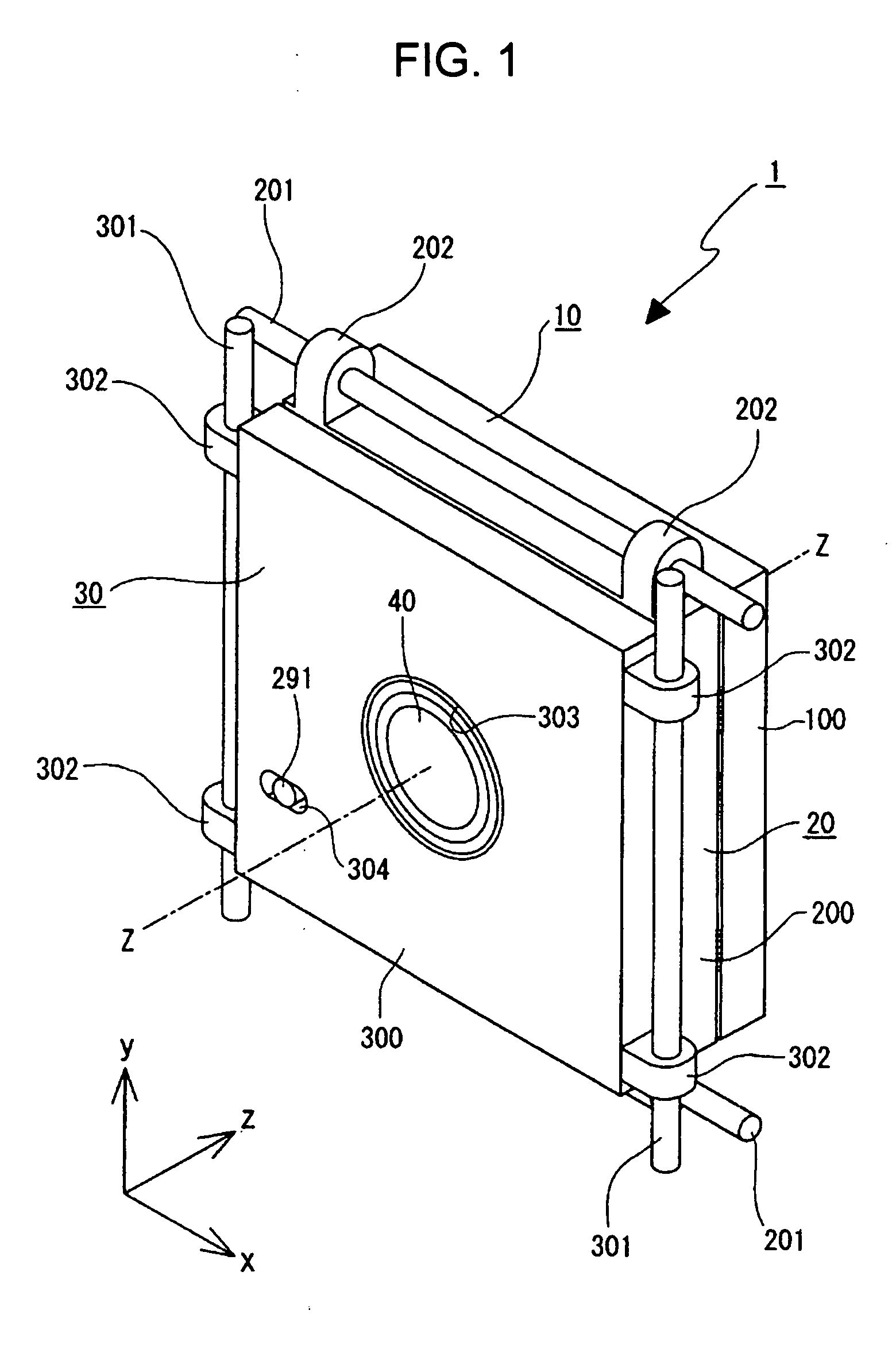
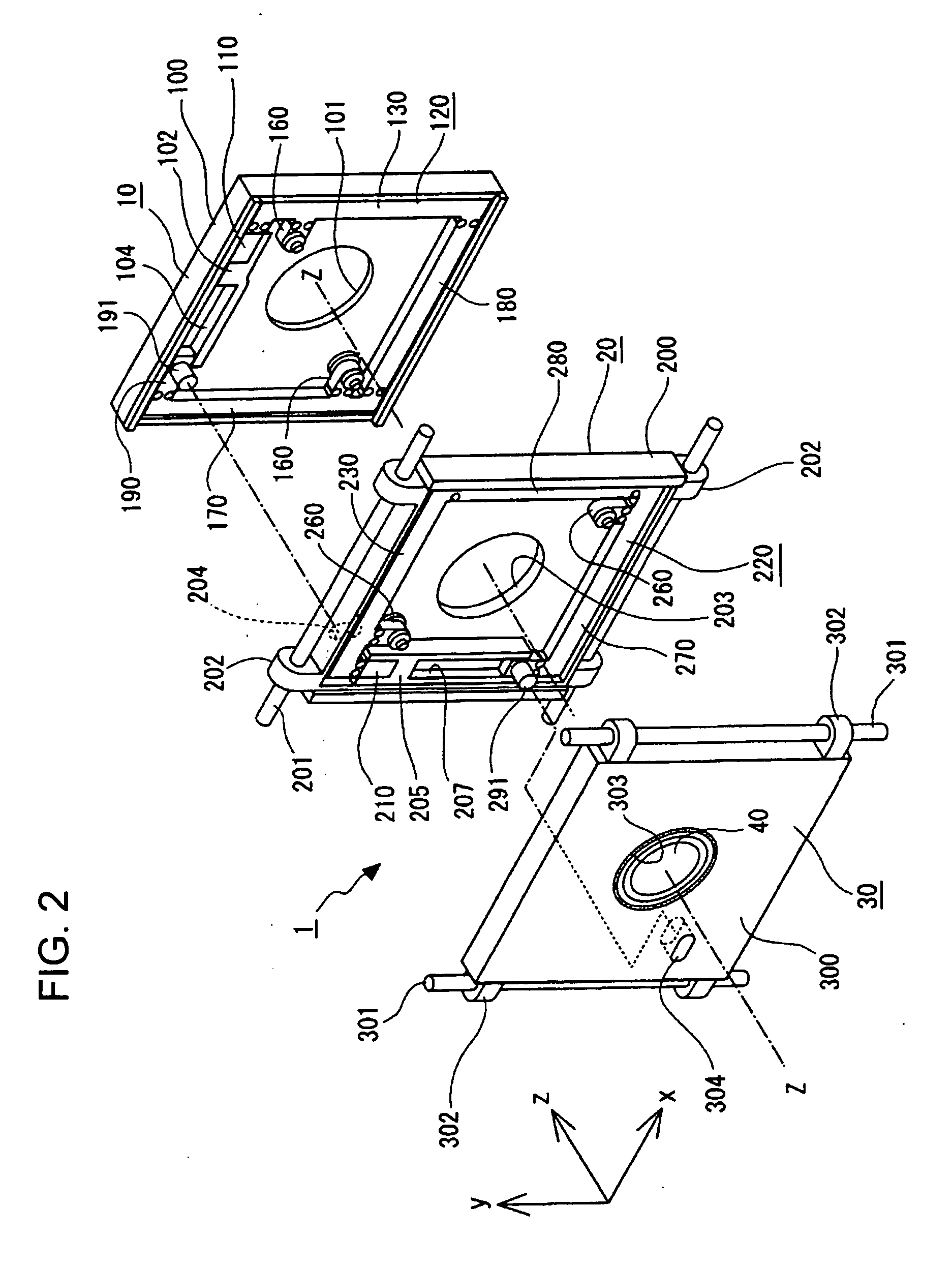
[0052] A lens driving mechanism 1 includes three blocks, a stationary block 10, a first movable block 20, and a second movable block 30. The stationary block 10 is fixedly supported at a lens barrel (not shown). The first movable block 20 is movable in one direction perpendicular to an optical axis with respect to the lens barrel, that is, in an X direction with respect to the direction of arrow Z, defined as the optical axis direction, among the directions of arrows X, Y, and Z perpendicular to each other in FIG. 1, and the second movable block 30 is movable in the Y-axis direction perpendicular to the optical axis direction Z and the X-axis direction.

[0053] The stationary block 10 has a base table 100 serving as a stationary base. The base table...


PUM


Abstract

A lens driving mechanism for eccentrically driving at least one lens or lens subunit, hereunder called a correcting lens, in a lens system constituting a taking lens unit in a plane perpendicular to an optical axis direction includes an electro-mechanical conversion element and a link mechanism. The electro-mechanical conversion element is fixedly disposed at a lens barrel where the taking lens unit is disposed, and is mechanically deformed by an application of a voltage. The link mechanism increases the mechanical deformation of the electro-mechanical conversion element and transmits the increased mechanical deformation to the correcting lens, and is disposed around the correcting lens at the outer side of an effective diameter of the correcting lens when viewed in the optical axis direction.

Description

CROSS REFERENCES TO RELATED APPLICATIONS [0001] The present invention contains subject matter related to Japanese Patent Application JP 2004-171095 filed in the Japanese Patent Office on Jun. 9, 2004, the entire contents of which are incorporated herein by reference. BACKGROUND OF THE INVENTION [0002] 1. Field of the Invention [0003] The present invention relates to a novel lens driving mechanism. More specifically, the present invention relates to a technology which uses a lens driving mechanism suitable for an optical camera movement correcting mechanism mounted in, for example, a video camera or a digital still camera and which can reliably increase to a required stroke a very small displacement of an electro-mechanical converting element (such as a piezoelectric element) and transmit the increased displacement to a lens. [0004] 2. Description of the Related Art [0005] The optical camera movement correcting mechanism detects a camera movement in a direction perpendicular to an op...

Claims


Application Information

Patent Timeline
IPC IPC(8): G02B7/02G03B5/00G02B27/64G03B17/00H04N5/225H04N5/232
CPCG02B27/646H04N5/23287H04N5/23248H04N5/2254H04N23/55H04N23/661H04N23/68H04N23/687
Inventor TSUTSUMI, TAKUYA
Owner SONY CORP
Why Eureka
Try Eureka