Guided fluid driven turbine

Inactive Publication Date: 2005-12-15
YANG TAI HER
View PDF8 Cites 9 Cited by
  • Summary
  • Abstract
  • Description
  • Claims
  • Application Information

AI Technical Summary

Benefits of technology

[0005] The primary purpose of the present invention is to provide a guided fluid driven turbine that upgrades the efficiency in converting fluid kinetics into rotation kinetics. To achieve the purpose, a specific directional guide unit is adapted to

Problems solved by technology

The wind resistance (Cd) of the conventional structure of an outflanking guide hood indicates comparatively higher and the higher wind r

Method used


Image

  • Guided fluid driven turbine
  • Guided fluid driven turbine
  • Guided fluid driven turbine

Examples


Embodiment Construction

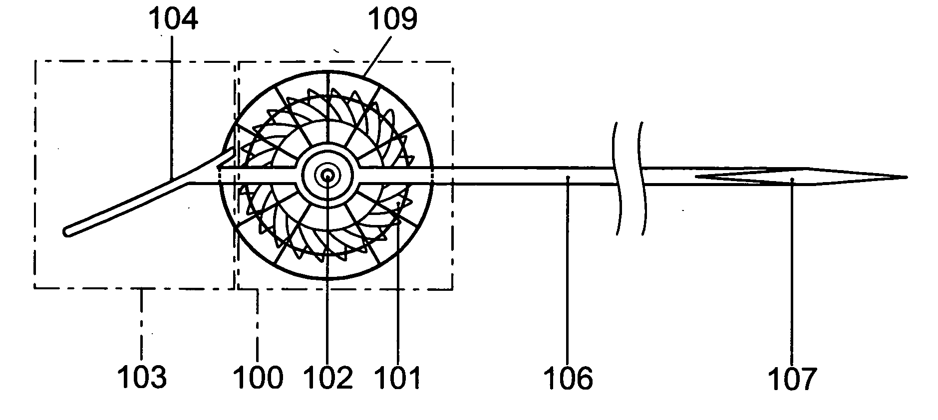
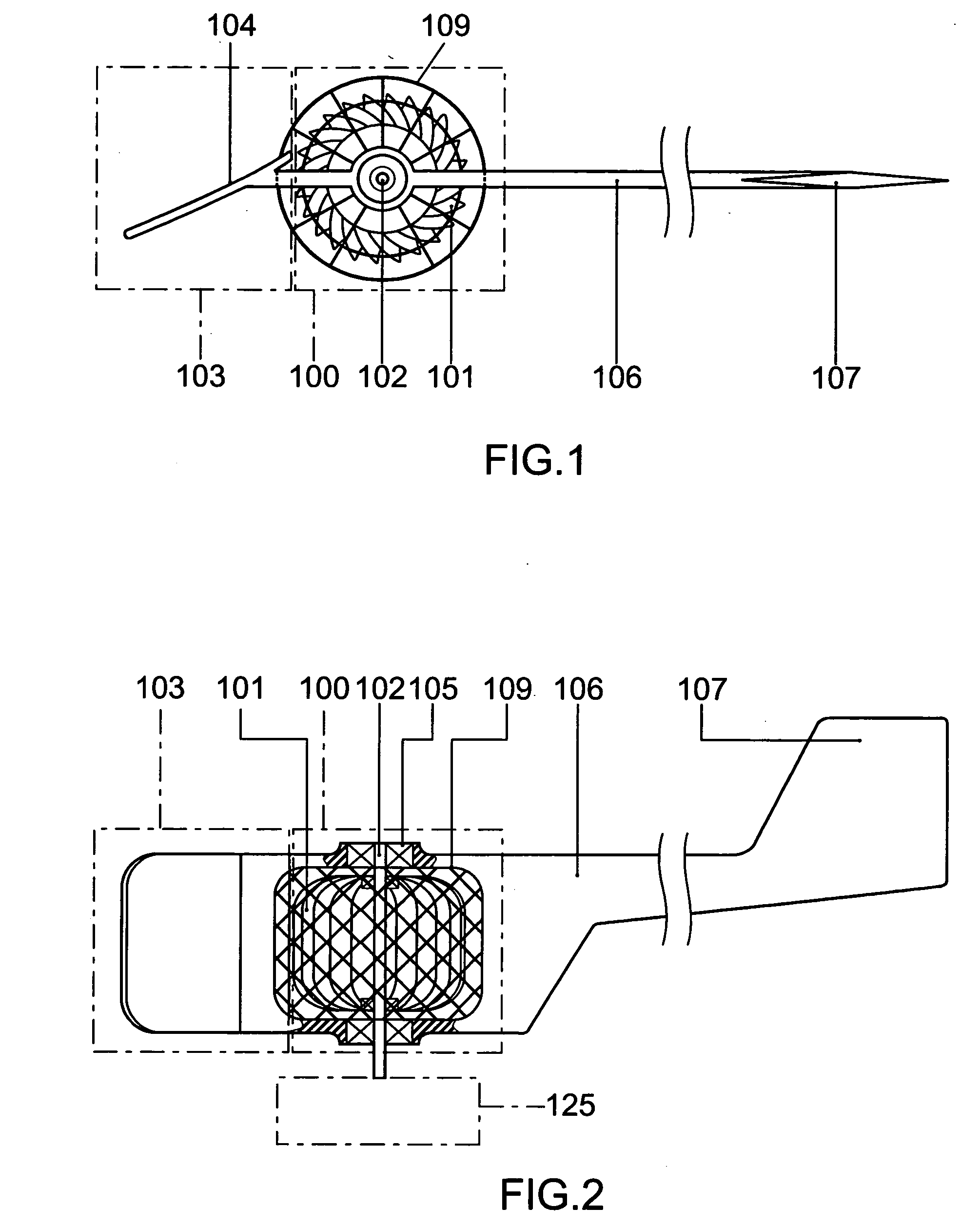
[0029] The purpose of the present invention is to provide a guided fluid driven turbine. To achieve the purpose, an open specific directional guide hood extending along the load side from head to tail of the turbine is provided to the turbine to guide the fluid by compromising the flowing direction of the fluid, thus to change the fluid pressure on the load side of the turbine.

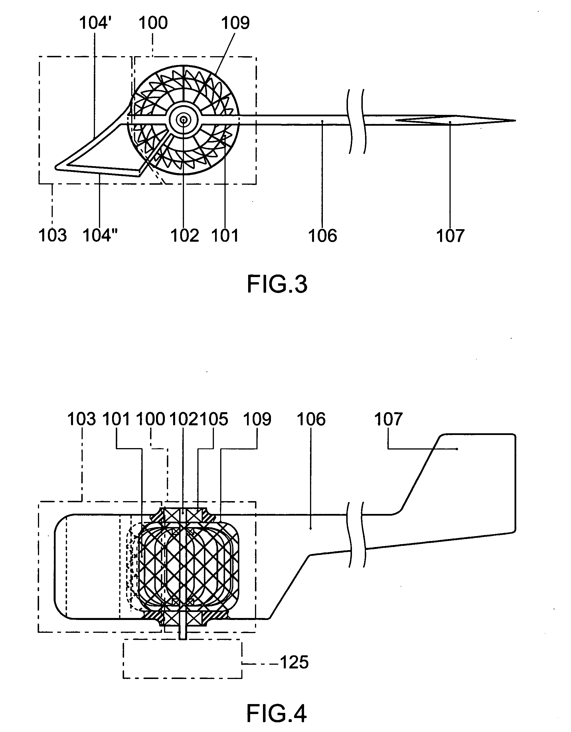
[0030] Depending on working principles of the open-end, single side guide structure extending backwards from its head that meets the fluid source along the load side of the turbine, this guided fluid driven turbine may be provided in any of the following structural types: [0031] 1) The specific directional guide unit is in a structure of a single plate of pressure boosting guide as illustrated in FIGS. 1 and 2; [0032] 2) The Specific directional guide unit is in a structure of a dual-plate containing a pressure boosting guide and a pressure reduction guide as illustrated in FIGS. 3 and 4; [0033] 3) The Specif...


PUM


Abstract

A guided fluid driven turbine to upgrade the efficiency in converting fluid kinetics into rotation kinetics by having a specific directional guide unit adapted to a fluid driven turbine for the fluid to be guided the open-end, specific directional guide unit extending from its head along the load side of the turbine, thus to change the fluid pressure on the load surface of the turbine.

Description

BACKGROUND OF THE INVENTION [0001] (a) Field of the Invention [0002] The present invention is related to a guided fluid driven turbine, and more particularly, to a fluid driven turbine adapted to its peripheral an open-end, specific directional guide unit extending from its head along the load side of the turbine to guide the fluid, thus to change the fluid pressure thereon to upgrade the efficiency in converting fluid kinetics into rotation kinetics. [0003] (b) Description of the Prior Art [0004] The wind resistance (Cd) of the conventional structure of an outflanking guide hood indicates comparatively higher and the higher wind resistance of the prior art makes the prior art less favorable to operate in an environment present with higher wind velocity or fluidity. SUMMARY OF THE INVENTION [0005] The primary purpose of the present invention is to provide a guided fluid driven turbine that upgrades the efficiency in converting fluid kinetics into rotation kinetics. To achieve the pu...

Claims


Application Information

Patent Timeline
IPC IPC(8): F03B17/06F03D3/04F03D7/00
CPCF03B17/063F03D3/0472Y10S415/907Y02E10/28Y02E10/74F03D3/0481F03D3/02Y02E10/20
Inventor YANG, TAI-HER
Owner YANG TAI HER
Why Eureka
Try Eureka