
Steel plate reinforcing sheet

a technology of reinforcing sheet and steel plate, which is applied in the direction of synthetic resin layered products, transportation and packaging, chemistry apparatus and processes, etc., can solve the problems of reducing the reinforcing property of steel plate reinforcing sheet and the difference in the thermal expansion coefficient between the laminated adhesive layers, so as to reduce the distortion of steel pla

Inactive Publication Date: 2005-12-15
NITTO DENKO CORP
View PDF3 Cites 7 Cited by
  • Summary
  • Abstract
  • Description
  • Claims
  • Application Information

AI Technical Summary

Benefits of technology

[0010] It is an object of the present invention to provide a steel plate reinforcing sheet that can reduce distortions of the steel plate without reducing its reinforcing property and can also prevent abrupt deformations at end portions thereof with respect to a direction extending along a curving direction of a curved steel plate.
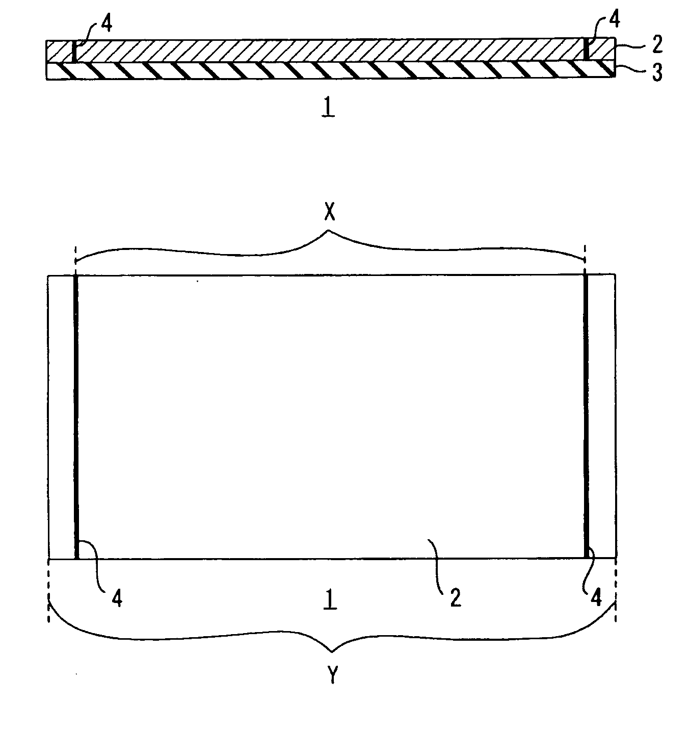
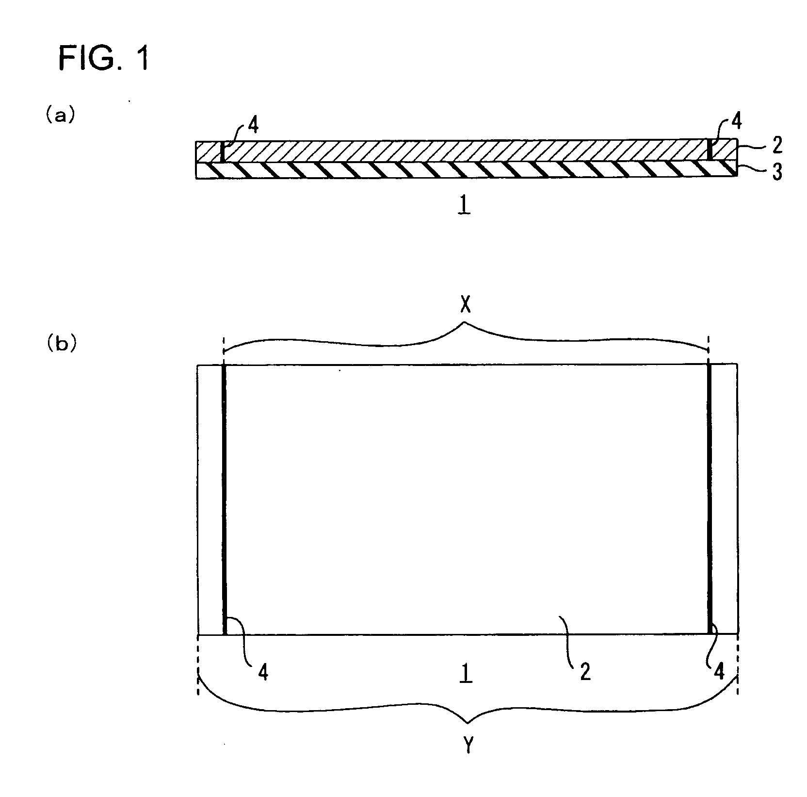
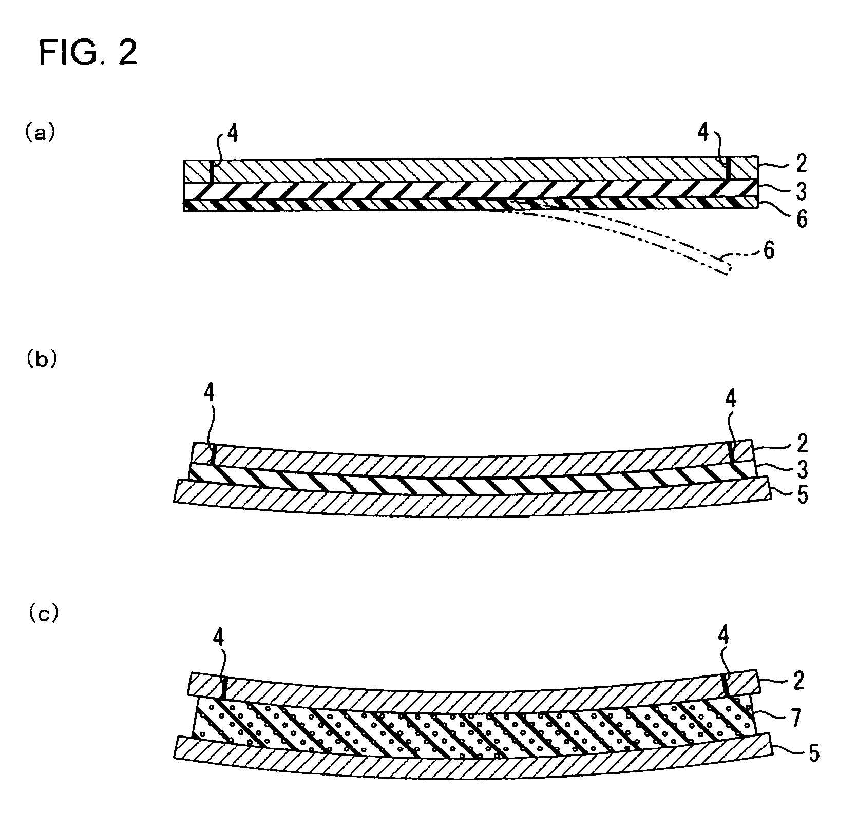
[0026] According to the steel plate reinforcing sheet of the present invention, the slits are formed in both end portions of the restricting layer to extend over an entire length of the restricting layer with respect to a direction substantially orthogonal to a direction in which the both end portions confront each other so that a length defined between the slits can be 40% or more of a total length of the steel plate reinforcing sheet with respect to a direction parallel to the length between the slits. This arrangement can produce the result that when the steel plate reinforcing sheet is adhesively bonded to the curved steel plate so that the slits extend along a direction substantially orthogonal to the curving direction of the curved steel plate and then the reinforcing layer is foamed, in order to reinforce the curved steel plate, the slits can allow the stress concentrated on the end portions of the steel plate reinforcing sheet to be relieved from those end portions. As a result, even when the steel plate reinforcing sheet is applied to the curved steel plate, abrupt deformation of the end portions of the steel plate reinforcing sheet with respect to the direction extending along the curving direction of the curved steel plate can be prevented. This can provide reduction of distortions of the steel plate, while providing the reliable reinforcement.

Problems solved by technology

However, this thermally curable adhesive sheet for reinforcing the thin steel plate has the disadvantage that when cooled, distortions caused by difference in thermal expansion coefficient between the laminated adhesive layers occur in the steel plate (adherend).
The formation of the staggered slits can provide the advantage of reducing the distortions of the steel plate, while on the other hand, it provides the disadvantage of reducing the reinforcing property of the steel plate reinforcing sheet.

Method used


Image

  • Steel plate reinforcing sheet
  • Steel plate reinforcing sheet
  • Steel plate reinforcing sheet

Examples


example 1

[0134] The laminated sheet produced in the manner described above was cut to a rectangular form of 100 mm wide and 50 mm long, as shown in FIG. 3(b). Then, two slits 4 having a width of 0.05 mm were formed in both widthwise end portions of the laminated sheet with a cutter, to extend through the restricting layer 2 in a thickness direction thereof, as shown in FIG. 3(a), to thereby produce the steel plate reinforcing sheet 1.

[0135] The slits 4 were formed, at locations 10 mm widthwise inward from the both widthwise ends of the steel plate reinforcing sheet 1, to extend over the entire length thereof in the longitudinal direction, respectively, so as to be a symmetric and parallel-lines form as viewed from top, as shown in FIG. 3(b). In this steel plate reinforcing sheet 1, a widthwise length defined between the slits 4 was set to be 80% of a total widthwise length of the steel plate reinforcing sheet 1 throughout the entire longitudinal dimension thereof.

example 2

[0136] The laminated sheet produced in the manner described above was cut to a rectangular form of 100 mm wide and 50 mm long, as shown in FIG. 4(b). Then, two slits 4 having a width of 0.05 mm were formed in both widthwise end portions of the laminated sheet with the cutter, to extend through the restricting layer 2 in a thickness direction thereof, as shown in FIG. 4(a), to thereby produce the steel plate reinforcing sheet 1.

[0137] The slits 4 were formed, at locations 15 mm widthwise inward from the both widthwise ends of the steel plate reinforcing sheet 1, to extend over the entire length thereof in the longitudinal direction, respectively, so as to be a symmetric and parallel-lines form as viewed from top, as shown in FIG. 4(b). In this steel plate reinforcing sheet 1, a widthwise length defined between the slits 4 was set to be 70% of a total widthwise length of the steel plate reinforcing sheet 1 throughout the entire longitudinal dimension thereof

example 3

[0138] The laminated sheet produced in the manner described above was cut to a rectangular form of 100 mm wide and 50 mm long, as shown in FIG. 5(b). Then, two slits 4 having a width of 0.05 mm were formed in both widthwise end portions of the laminated sheet with the cutter, to extend through the restricting layer 2 in a thickness direction thereof, as shown in FIG. 5(a), to thereby produce the steel plate reinforcing sheet 1.

[0139] The slits 4 were formed to extend between locations on one lengthwise side of the steel plate reinforcing sheet 1 10 mm widthwise inward from the both widthwise ends thereof and related locations on the other lengthwise side thereof 20 mm widthwise inward from the both widthwise ends thereof, to extend over the entire length thereof in the longitudinal direction, respectively, so as to be a symmetric and tapered form as viewed from top, as shown in FIG. 5(b). In this steel plate reinforcing sheet 1, a narrowest (shortest) widthwise dimension defined be...


PUM

PropertyMeasurementUnit
widthsaaaaaaaaaa
thicknessaaaaaaaaaa
thicknessaaaaaaaaaa

Abstract

A steel plate reinforcing sheet that can reduce distortions of the steel plate without reducing its reinforcing property and can also prevent abrupt deformations at end portions thereof with respect to a direction extending along a curving direction of a curved steel plate. The steel plate reinforcing sheet 1 comprising a restricting layer 2 and a reinforcing layer 3, wherein slits 4 are formed in both end portions of the restricting layer 2 to extend over an entire length of the restricting layer 2 with respect to a direction substantially orthogonal to a direction in which the both end portions confront each other and also arranged so that a length defined between the slits 4 can be 40% or more of a total length of the steel plate reinforcing sheet 1 with respect to a direction parallel to the length between the slits 4. Then, the steel plate reinforcing sheet 1 is adhesively bonded to the curved steel plate 5 so that the slits 4 extend along a direction substantially orthogonal to the curving direction of the curved steel plate 5 and, then, is foamed and cured.

Description

BACKGROUND OF THE INVENTION [0001] 1. Field of the Invention [0002] The present invention relates to a steel plate reinforcing sheet and, more particularly, to a steel plate reinforcing sheet to be adhesively bonded to a steel plate used in a variety of industrial machines, such as transportation machines, to reinforce the steel plate. [0003] 2. Description of the Prior Art [0004] In general, the steel plate for a shell of an automotive vehicle is manufactured in the form of a thin sheet having a thickness generally in the range of 0.6 mm to 0.8 mm, for reduction in weight of a vehicle body. As is known, the steel plate reinforcing sheet used for reinforcing the steel plate comprises a restricting layer and a reinforcing layer. In use, the steel plate reinforcing sheet is adhesively bonded to the inside of the steel plate and then the reinforcing layer is foamed. [0005] A thermally curable adhesive sheet for reinforcing a thin steel plate was proposed as the steel plate reinforcing ...

Claims


Application Information

Patent Timeline
Patent Type & Authority Applications(United States)
IPC IPC(8): B32B3/10B32B5/18B32B3/30B32B15/08B32B15/18B32B25/04B32B27/38
CPCB32B3/10B32B15/08Y10T428/24298Y10T428/24314B32B15/18Y10T428/31529Y10T428/31678Y10T428/31696Y10T428/31522Y10T428/31692Y10T428/31855B32B15/046B32B2309/10B32B2305/022B32B5/18
Inventor KAGEHISA, YUKIERIGUCHI, FUYUKIAKAMATSU, HIDEKI
Owner NITTO DENKO CORP
Learn More