Redundant processing architecture for single fault tolerance

Active Publication Date: 2005-12-15
HONEYWELL INT INC
View PDF33 Cites 31 Cited by
  • Summary
  • Abstract
  • Description
  • Claims
  • Application Information

AI Technical Summary

Benefits of technology

[0005] Embodiments of the present invention address enhancing the spe

Problems solved by technology

At times, electronic systems can operate outside normal parameters thereby producing faulty data.
In some circumstances, failure of these systems can be catastrophic.
Although radiation harde

Method used


Image

  • Redundant processing architecture for single fault tolerance
  • Redundant processing architecture for single fault tolerance
  • Redundant processing architecture for single fault tolerance

Examples


Example

[0012] In the following detailed description of the preferred embodiments, reference is made to the accompanying drawings that from a part hereof, and in which is shown by way of illustration specific embodiments in which the invention may be practiced. It is to be understood that other embodiments may be utilized and structural changes may be made without departing from the scope of the present invention.

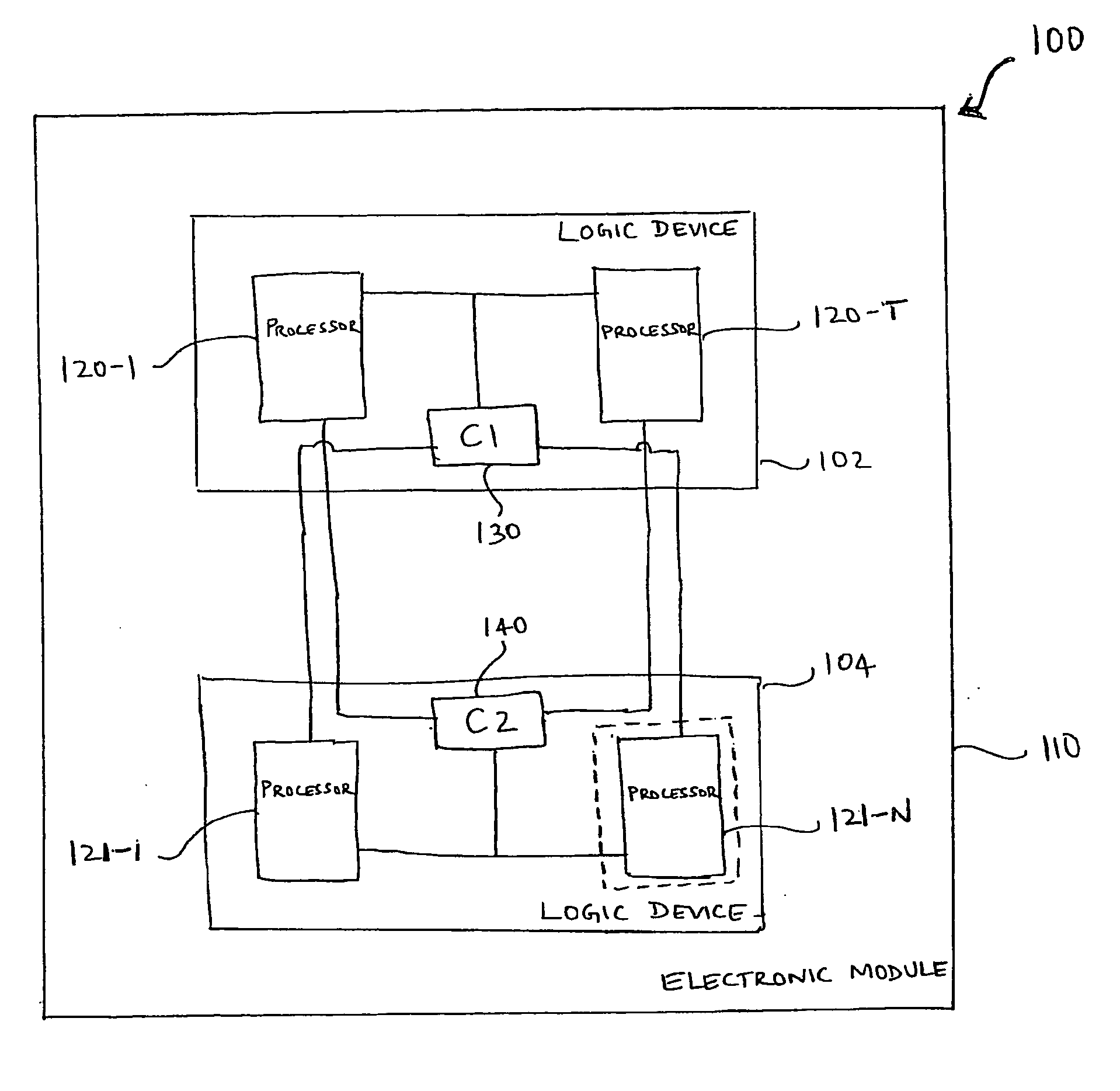
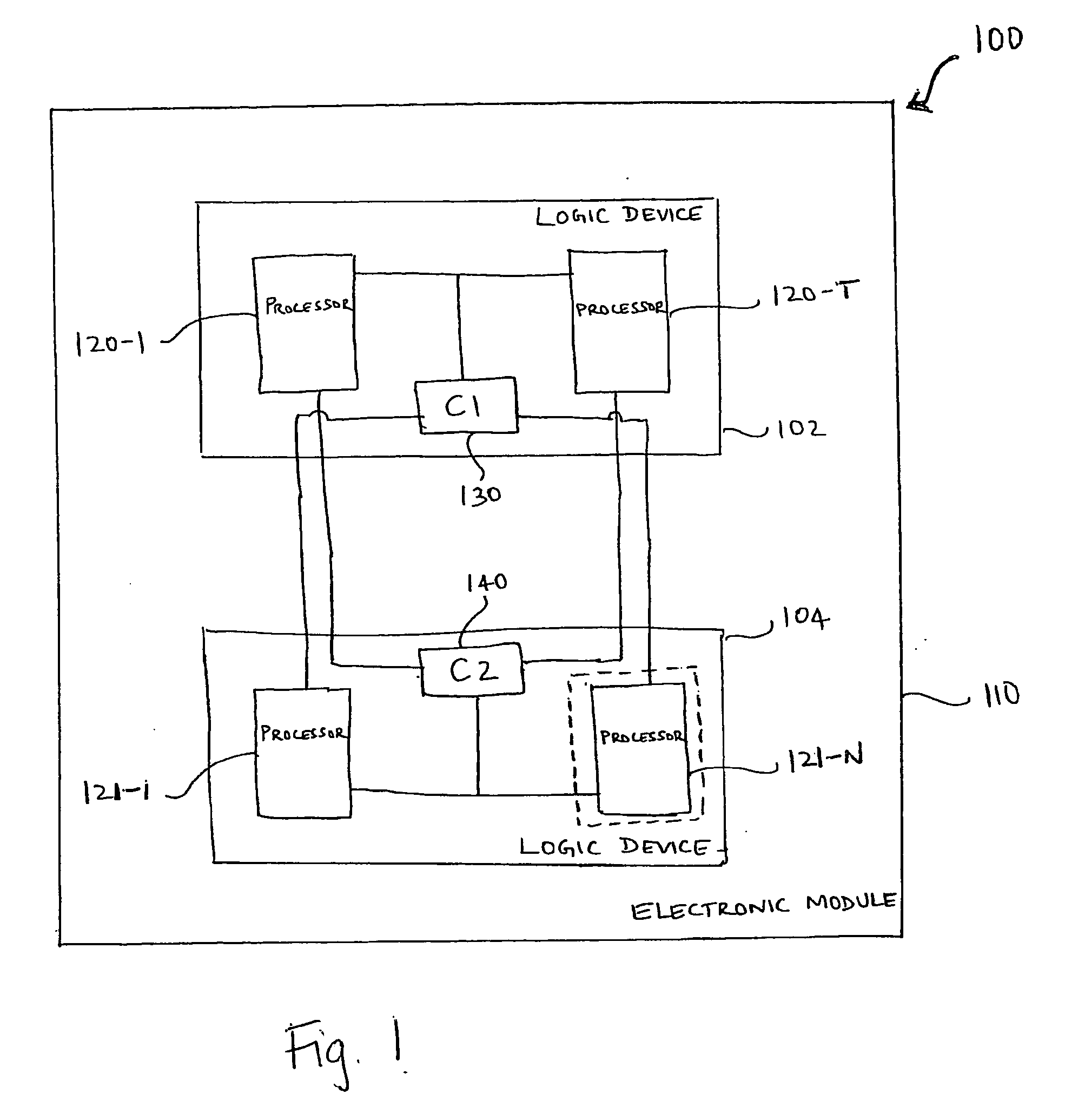
[0013]FIG. 1 is a block diagram of the architecture of one embodiment of an electronic module 110, indicated generally at 100 according to the teachings of the present invention. Electronic module 110 includes a single fault tolerant architecture having first and second, redundant logic devices 102 and 104. In one embodiment, the electronic module 110 is an Application Specific Integrated Chip (ASIC). In another embodiment, the electronic module 110 is a Printed Wired Assembly (PWA).

[0014] In one embodiment, logic devices 102 and 104 are field programmable gate arrays (FPGAs) tha...


PUM


Abstract

An electronic module is provided. The module includes a first logic device having at least two processors and a first comparator and a second logic device having at least one processor and a second comparator. Each of the at least two processors are coupled to each of the first and second comparators. The first and second comparators operate as a distributed comparator system. Each comparator independently identifies faults in the processors.

Description

TECHNICAL FIELD [0001] The present invention relates generally to the field of redundant architectures, and in particular, to developing a single fault tolerant architecture. BACKGROUND INFORMATION [0002] Space missions require the highest upset rate immunity available to overcome Single Event Upsets (SEUs). At times, electronic systems can operate outside normal parameters thereby producing faulty data. In some circumstances, failure of these systems can be catastrophic. Although radiation hardened processors are available, they offer lower performance and higher cost than commercial off the shelf processors. In order to use non-hardened devices, a fault tolerant scheme is used in architectures that include one or more redundant systems. To identify the faulty system, voting mechanisms are used. The voting mechanisms process the simultaneous outputs of the redundant systems to determine the system producing the correct data. The voting mechanisms used in these architectures are imp...

Claims


Application Information

Patent Timeline
IPC IPC(8): G06F11/00G06F11/18
CPCG06F11/1658G06F11/182G06F11/187G06F11/185G06F11/184
Inventor WOLFE, JEFFREY M.COPENHAVER, JASON L.RAMOS, JEREMY
Owner HONEYWELL INT INC
Why Eureka
Try Eureka