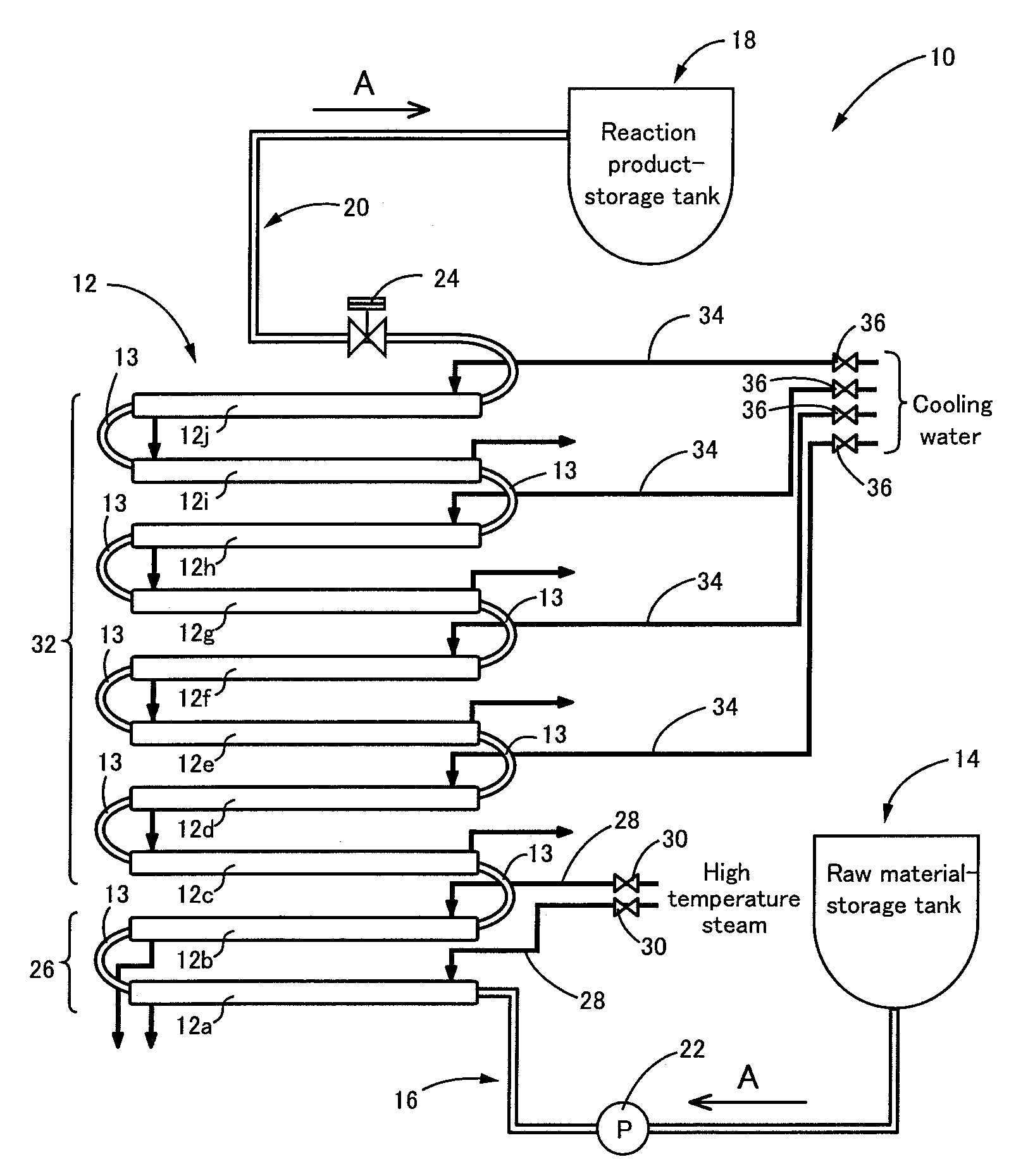
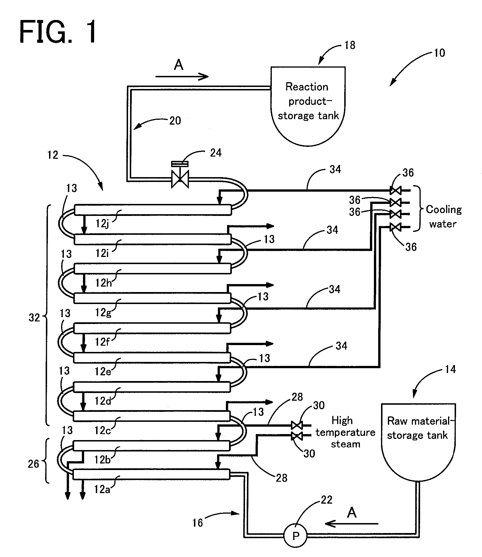
[0022] According to the above-mentioned first form of the process for producing the phenolic novolak resin according to the present invention, the heating zone is provided on the upstream side of a longitudinal reaction tube, in the direction of the flow of the mixture (liquid) of the raw materials, and the mixture is promptly heated to a temperature, which is not less than the temperature, at which the reaction heat is generated. In this case, in the present invention, it is desirable to adopt, as a minimum
heating temperature, a temperature (about 80° C.˜about 100° C.), with which an addition
condensation reaction is substantially initiated and a sufficient reaction heat is generated. Meanwhile, it is desirable to adopt, as a
maximum temperature, a temperature (about 160° C.˜about 180° C.), which enables the temperature control, although these temperatures are influenced by an amount and a kind of the catalyst. The temperature of thus heated mixture is controlled only by the cooling operation at a temperature
control zone, which is provided on the downstream side of the reaction tube with respect to the direction of the flow of the mixture, so as
not to exceed 180° C. and not to be lower than 90° C. For this reason, according to the present invention, the phenolic novolak resin which has a desired molecular weight can be highly advantageously produced. In addition, according to the present invention, a speed of the production of the intended resin is enhanced, whereby a distribution of molecular weight of thus produced resin is preferable, and a generation of the higher order condensation products to be the scale is effectively restrained, compared with a conventional method, in which the temperature is gradually increased. In the present invention, the “temperature, at which the reaction heat is generated” means a temperature, at which a
rate of increase of the mixture temperature at the heating zone is enhanced.
[0023] In addition, in the process for producing the phenolic novolak resin according to the present invention, the pressure in the reaction tube is kept to be not lower than the
vapor pressure of water. Accordingly, there is advantageously restricted a
vaporization of water which is used as a
solvent and which is generated as a result of the
condensation reaction. Accordingly, the at least one of aldehydes is efficiently provided for the reaction, and there can be effectively prevented the unreacted at least one of aldehydes from remaining in the mixture, after the reaction is completed. Owing to this arrangement, there is not needed to previously introduce a somewhat larger quantity of the at least one of aldehydes, anticipating a quantity of the at least one of aldehydes to be unreacted. In addition, there is not needed an operation of removing the unreacted at least one of aldehydes after the reaction, so that a production cost can be advantageously reduced.
[0024] Also, in the second form of the process for producing the phenolic novolak resin according to the present invention, the
pipe diameter of at least the portion of the reaction tube, which is located on the downstream side of the temperature
control zone with respect to the direction of the flow of the mixture, is made smaller than the
pipe diameter of the portion of the reaction tube which is located on the heating zone, so as to enhance the flow rate of the mixture located within the portion of the reaction tube of which the
pipe diameter is made smaller. Accordingly, even if a
viscosity of the mixture flowing at the downstream in the direction of the flow of the mixture is increased, there is highly effectively prevented the generation of the scale inside the reaction tube.
[0025] Moreover, according to the third form of the present invention, the
static mixer is positioned inside the reaction tube, so that the mixture being flowed in the reaction tube is stirred in the reaction tube. Accordingly, the reaction of the at least one of phenols with the at least one of aldehydes is effectively progressed, and the generation of the higher order condensation products can be effectively restrained.
[0026] In addition, if the flow rate of the mixture is not less than 0.3 m / second according to the above fourth form of the process for producing the phenolic novolak resin of the present invention, there can be more effectively prevented the generation of the higher order condensation products.
[0027] Also, in the fifth form of the process for producing the phenolic novolak resin according to the present invention, the length of the heating zone is shorter than the length of the temperature
control zone, so that the mixture of the raw materials is promptly heated to the temperature, which is not less than a temperature, at which the reaction heat is generated. Accordingly, there can be ensured a sufficient length of the temperature control zone, which progresses the reaction of the at least one of phenols with the at least one of aldehydes. Therefore, the intended phenolic novolak resin can be more advantageously produced.

