Apparatus and methods relating to fluorescent optical switches

a technology of optical switches and fluorescent light, applied in the field of optical switches, can solve the problems of reducing efficiency, loss of light, and sensitive effect of signal detection to alignment problems, and achieve the effect of enhancing sensitivity, speed or effectiveness

Inactive Publication Date: 2005-07-07
MACKINNON NICHOLAS B
View PDF5 Cites 6 Cited by
  • Summary
  • Abstract
  • Description
  • Claims
  • Application Information

AI Technical Summary

Benefits of technology

[0006] The present invention provides methods and apparatus that comprise optical switches that take advantage of fluorescence to enhance sensitivity, 'speed or effectiveness. In some embodiments, the present invention provides a target area comprising at least one target surface comprising a fluorophore-containing target material, wherein the target surface comprises at least a first target area that provides a first fluorescent response when illuminated by excitation light and a second target area that provides a second light response when illuminated; the second response can be either reflectance light or fluorescent light, or other desired light response. The excitation light can be optically guided to the target via an optical fiber or other optical light guide. The switch can detect the resulting fluorescent light emitted from the target, for example by collecting the light into an optical fiber or other optical light guide and optically guiding it to the detector. The detector, which in this embodiment can include an operably connected computer, spectrometer, spectrograph or other optical analyzer, measures at least one of the relative intensity or wavelength of the response from the target, such as the induced fluorescence emission of the first target area, then determines the presence or type of the fluorescence.

Problems solved by technology

The development of optical switches, including fiber optic switches, has been a result of a need to avoid electrical power in certain control lines because electrical switches in such situations can, for example, cause explosions in an explosive atmosphere and shocks if in the presence of liquid.
For some optical switches, for example those containing a mirror actuator, the coupling efficiency of the reflected light and, therefore, the effectiveness of the signal detection is sensitive to alignment problems.
In systems in which there is a gap between an end of the fiber and the mirror, the surfaces of the fiber and mirror may be prone to contamination, which can lead to each of back scattering and contamination, which in turn can lead to loss of light and hence reduced efficiency.
Back scattering at any of the other optical interfaces can create additional noise in the optical signal and require additional signal processing or detector compensation to accurately detect the state of the switch.
This higher energy level is usually unstable.

Method used


Image

  • Apparatus and methods relating to fluorescent optical switches
  • Apparatus and methods relating to fluorescent optical switches
  • Apparatus and methods relating to fluorescent optical switches

Examples


Embodiment Construction

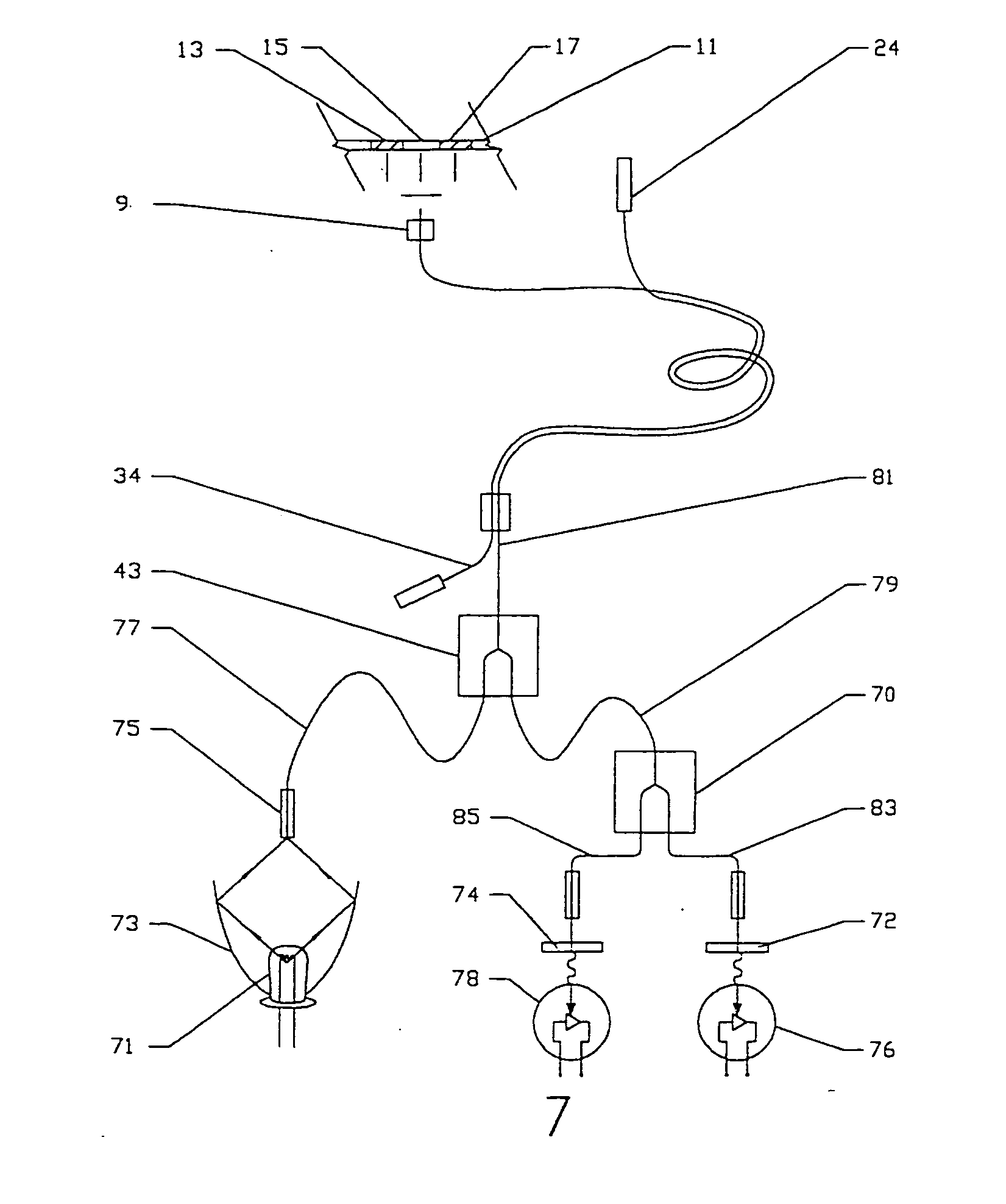
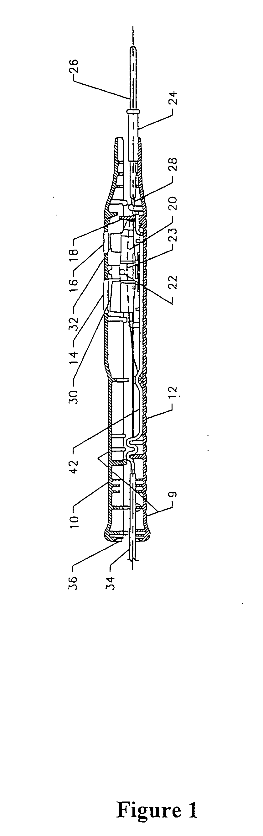
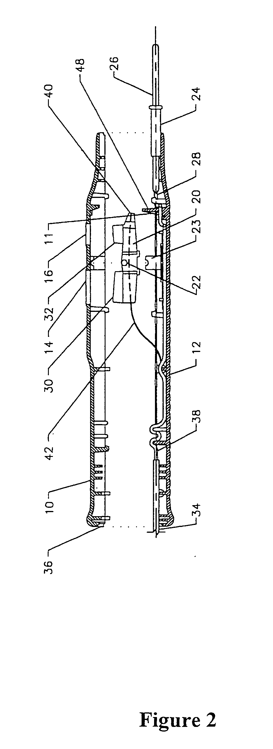
[0059] The present invention provides methods and apparatus that comprise optical switches that take advantage of fluorescence to enhance sensitivity, speed or effectiveness. In some embodiments, the present invention provides a target area comprising at least one target surface comprising a fluorophore-containing target material, wherein the target surface comprises at least a first target area that provides a first fluorescent response when illuminated by excitation light and a second target area that provides a second light response when illuminated; the second response can be either reflectance light or fluorescent light, or other desired light response. The excitation light can be optically guided to the target via an optical fiber or other optical light guide. The switch can detect the resulting fluorescent light emitted from the target, for example by collecting the light into an optical fiber or other optical light guide and optically guiding it to the detector. The detector...


PUM

PropertyMeasurementUnit
optical responsesaaaaaaaaaa
fluorescentaaaaaaaaaa
fluorescenceaaaaaaaaaa

Abstract

A fiber optic switching system which includes an optical switch having a movable actuator and a light fiber coupled to the actuator which terminates at an end target surface thereof for conducting excitation light from a light source to the optical switch mechanism. A flexible film or other surface whose response is conditioned to provide at least two different fluorescent surfaces is positioned such that an end surface of the actuator abuts or is placed in close proximity to the film throughout its movement from one position to another. A detector detects light emitted from the film. The actuator is movable so as to direct excitation light from the light fiber from the one fluorescent surface of the film to another and the detector detects light emitted from the film so as to determine which fluorescent surface of the film from which light has been emitted.

Description

CROSS-REFERENCE TO RELATED APPLICATIONS [0001] The present application claims priority from U.S. provisional patent application No. 60 / 188,653, filed Mar. 10, 2000.BACKGROUND [0002] The development of optical switches, including fiber optic switches, has been a result of a need to avoid electrical power in certain control lines because electrical switches in such situations can, for example, cause explosions in an explosive atmosphere and shocks if in the presence of liquid. Many optical switches are known in the art. See, e.g., U.S. Pat. No. 3,999,074; U.S. Pat. No. 4,045,667; U.S. Pat. No. 4,315,147; U.S. Pat. No. 4,904,044; U.S. Pat. No. 4,704,656; U.S. Pat. No. 5,892,862; U.S. Pat. No. 5,046,806. [0003] For some optical switches, for example those containing a mirror actuator, the coupling efficiency of the reflected light and, therefore, the effectiveness of the signal detection is sensitive to alignment problems. The mirror actuator mechanism typically locates the mirror surfa...

Claims


Application Information

Patent Timeline
Patent Type & Authority Applications(United States)
IPC IPC(8): G02B6/32G02B6/35G02B6/38
CPCG02B6/32G02B6/3552G02B6/3574G02B6/3845G02B6/359G02B6/381G02B6/3582
Inventor MACKINNON, NICHOLAS B.
Owner MACKINNON NICHOLAS B
Why Eureka
Try Eureka