Optoelectronic apparatus with a shielding cage, and methods for production of an optoelectronic apparatus with a shielding cage.

a technology of optoelectronic equipment and shielding cage, which is applied in the direction of electrical equipment, wave amplification devices, and semiconductor devices. it can solve the problems of undesirable design restrictions, complex and costly known technical solutions, and the inability to reduce the distance between the transmission module and the receiving module of the optical transceiver to the desired extent, etc., to achieve low cost and space-saving solutions. , the effect of low capacitan

Inactive Publication Date: 2005-12-22
INFINEON TECH AG
View PDF3 Cites 12 Cited by
  • Summary
  • Abstract
  • Description
  • Claims
  • Application Information

AI Technical Summary

Benefits of technology

[0007] The invention is based on the object of providing protection against electromagnetic interference radiation by means of a wire mesh which is integrated in the respective optoelectronic apparatus and/or the respective optoelectronic module. The integration of the wire mesh in the optoelectronic apparatus results in a low-cost and space-saving solution.
[0008] According to the invention, the wire mesh is at least partially embedded in the housing and, together with the leadframe, forms a shielding ...

Problems solved by technology

There is a general problem in providing electromagnetic shielding for optical transceivers and their transducer modules.
The known technical solutions are complex and costly.
The use of an external shielding plate also means...

Method used


Image

  • Optoelectronic apparatus with a shielding cage, and methods for production of an optoelectronic apparatus with a shielding cage.
  • Optoelectronic apparatus with a shielding cage, and methods for production of an optoelectronic apparatus with a shielding cage.
  • Optoelectronic apparatus with a shielding cage, and methods for production of an optoelectronic apparatus with a shielding cage.

Examples


Embodiment Construction

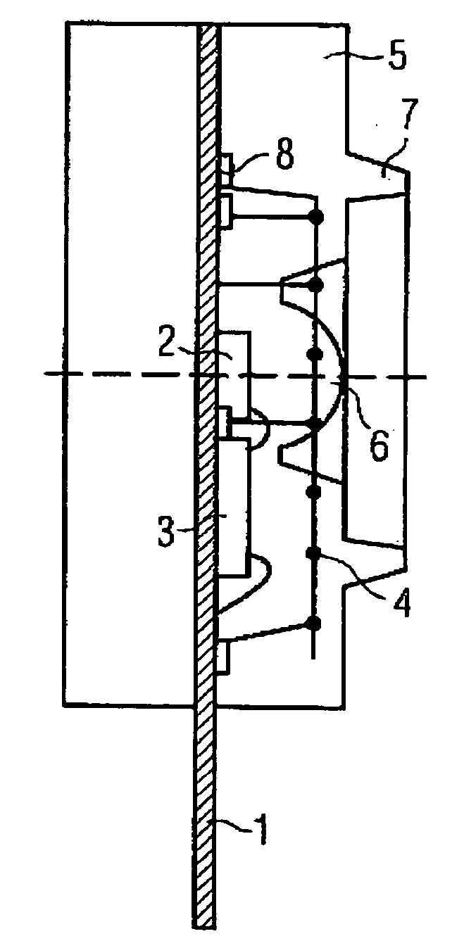
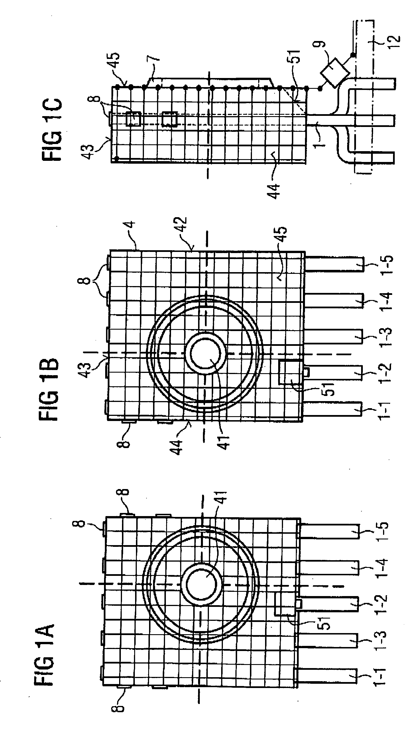
[0028] In order to assist understanding of the invention, the initial situation to which the invention relates will first of all be described with reference to FIGS. 4a and 4b.

[0029] As is shown in FIGS. 4a and 4b a receiving component 2 (which is in the form of a photodiode chip) and an electrical component 3 (which is associated with it) and is, for example a preamplifier IC, are arranged on a leadframe. The leadframe has a number of pins 1-1, 1-2, 1-3, 1-4, 1-5. The operating voltage VCC is provided via the pin 1-1, the ground contact via the pin 1-2, the signal SD (SD=Signal Detect) via the pin 1-3, and the differential received signal RD+, RD− via the pins 1-4 and 1-5.

[0030] The ground pin 1-2, which is also referred to as the ground lead 1-2, branches to a contact surface 1-28 for the components 2, 3 which are arranged on the leadframe 1, and to a large number of ground arms 1-21, 1-22, 1-23, 1-24, 1-25, 1-26, 1-27.

[0031] Contact is made with the photodiode chip 2 and with ...


PUM

PropertyMeasurementUnit
Diameteraaaaaaaaaa
Widthaaaaaaaaaa
Widthaaaaaaaaaa

Abstract

The invention relates to an optoelectronic apparatus in which a shielding cage is integrated in a housing to reduce electromagnetic interference. The invention further relates to methods for production of an optoelectronic apparatus having a shielding cage integrated into a housing portion thereof.

Description

[0001] The invention relates to an optoelectronic apparatus in which a shielding cage is integrated in order to reduce electromagnetic interference radiation. The invention furthermore relates to two methods for production of an optoelectronic apparatus such as this with an integrated shielding cage. BACKGROUND OF THE INVENTION [0002] There is a general problem in providing electromagnetic shielding for optical transceivers and their transducer modules. The transmission component of an optical transceiver must therefore be shielded owing to the electromagnetic radiation which it emits. The receiving element of an optical transceiver must be protected against incident electromagnetic radiation, in order to minimize the influence of interference radiation on signal detection. [0003] It is known for an external shielding plate, which is bent completely around the respective optical components, to be used for electromagnetic shielding. Furthermore, in order to reduce electromagnetic int...

Claims


Application Information

Patent Timeline
IPC IPC(8): G02B6/42H01L31/0203H01L31/0232
CPCH01L27/14625Y10T29/49002H01L31/0232H01L2224/48257H01L2224/48091H01L2224/48247H01L31/0203H01L2924/3025H01L2224/45147H01L2224/45124H01L2924/1815H01L2924/00014H01L2924/00H01L2924/207H01L2924/181H01L2224/48137H01L31/02325H01L2924/00011H01L2924/0002H01L2924/00012H01L2924/01005
Inventor SCHUNK, NIKOLAUS
Owner INFINEON TECH AG
Why Eureka
Try Eureka