Method and apparatus for operating an open-end rotor spinning unit

Inactive Publication Date: 2005-12-22
SAURER GERMANY GMBH & CO KG
View PDF6 Cites 8 Cited by
  • Summary
  • Abstract
  • Description
  • Claims
  • Application Information

AI Technical Summary

Benefits of technology

[0022] Regardless of the kind of electric quantity which is used to determine the rotation of the spinning rotor, it has shown that the electric quantity reaches a threshold value that can be used for a reliable determination of the state of closing of the

Problems solved by technology

In the case of spinning rotors that are driven by individual motors, in particular when these spinning rotors are s

Method used


Image

  • Method and apparatus for operating an open-end rotor spinning unit
  • Method and apparatus for operating an open-end rotor spinning unit
  • Method and apparatus for operating an open-end rotor spinning unit

Examples


Embodiment Construction

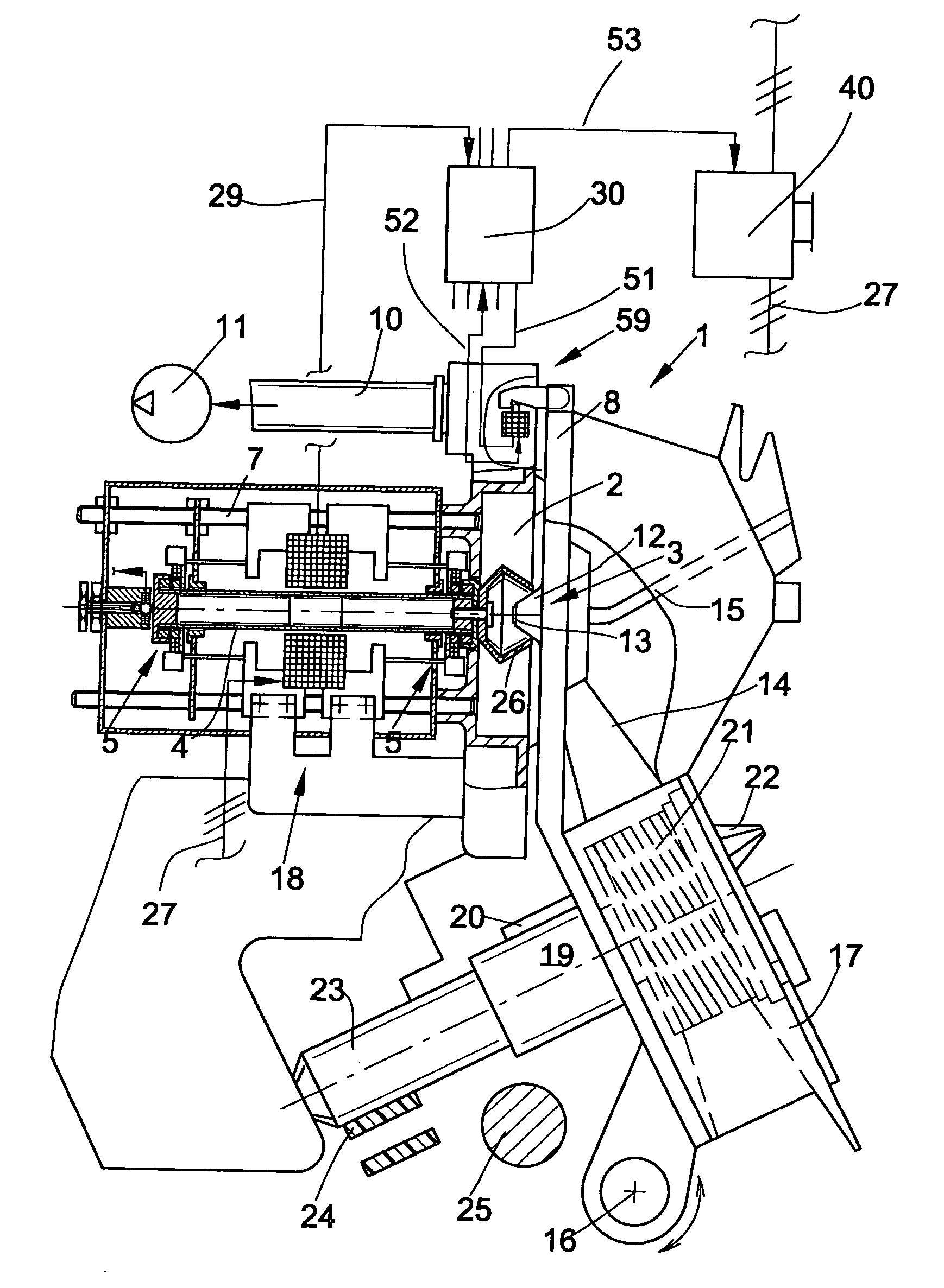
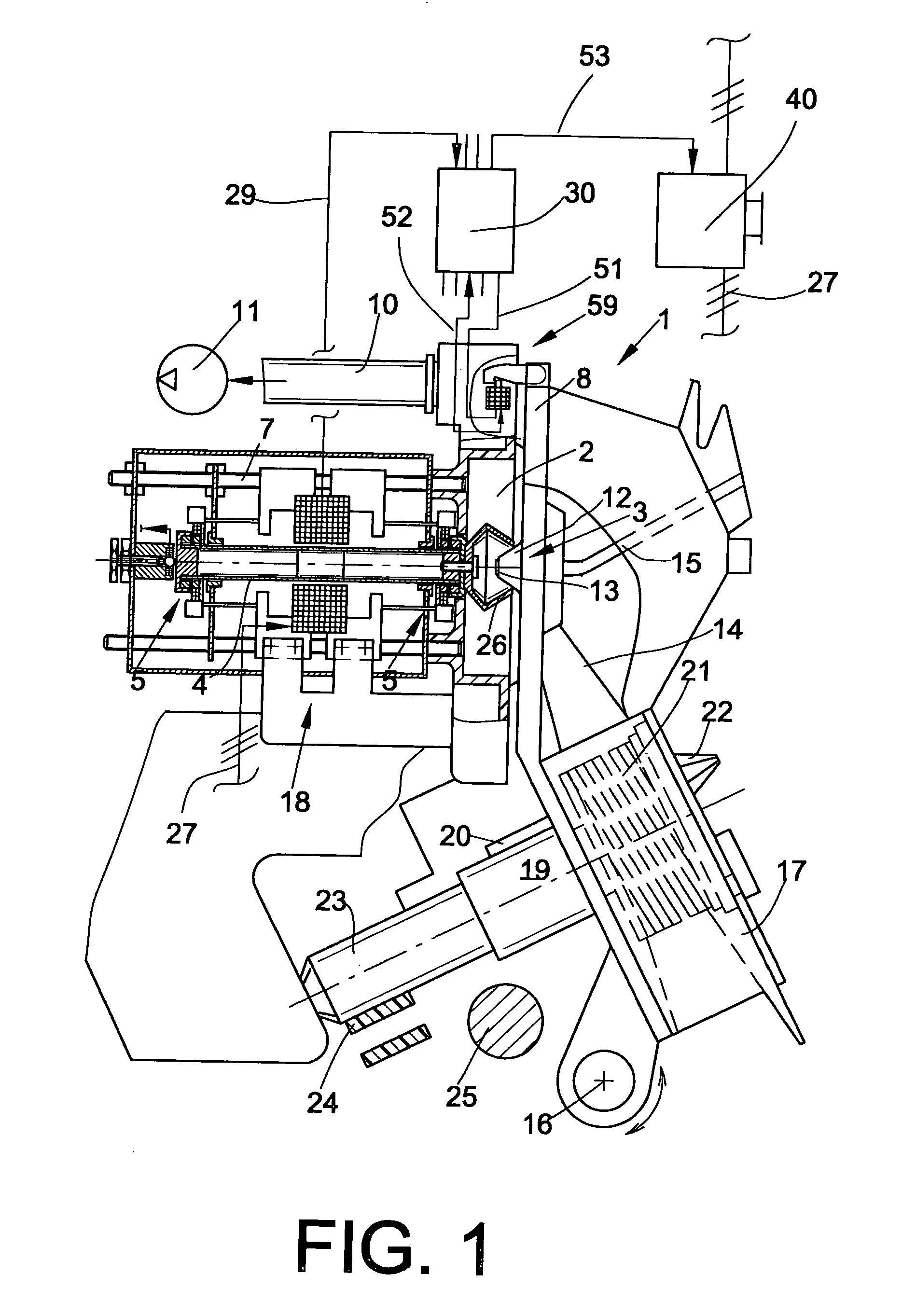
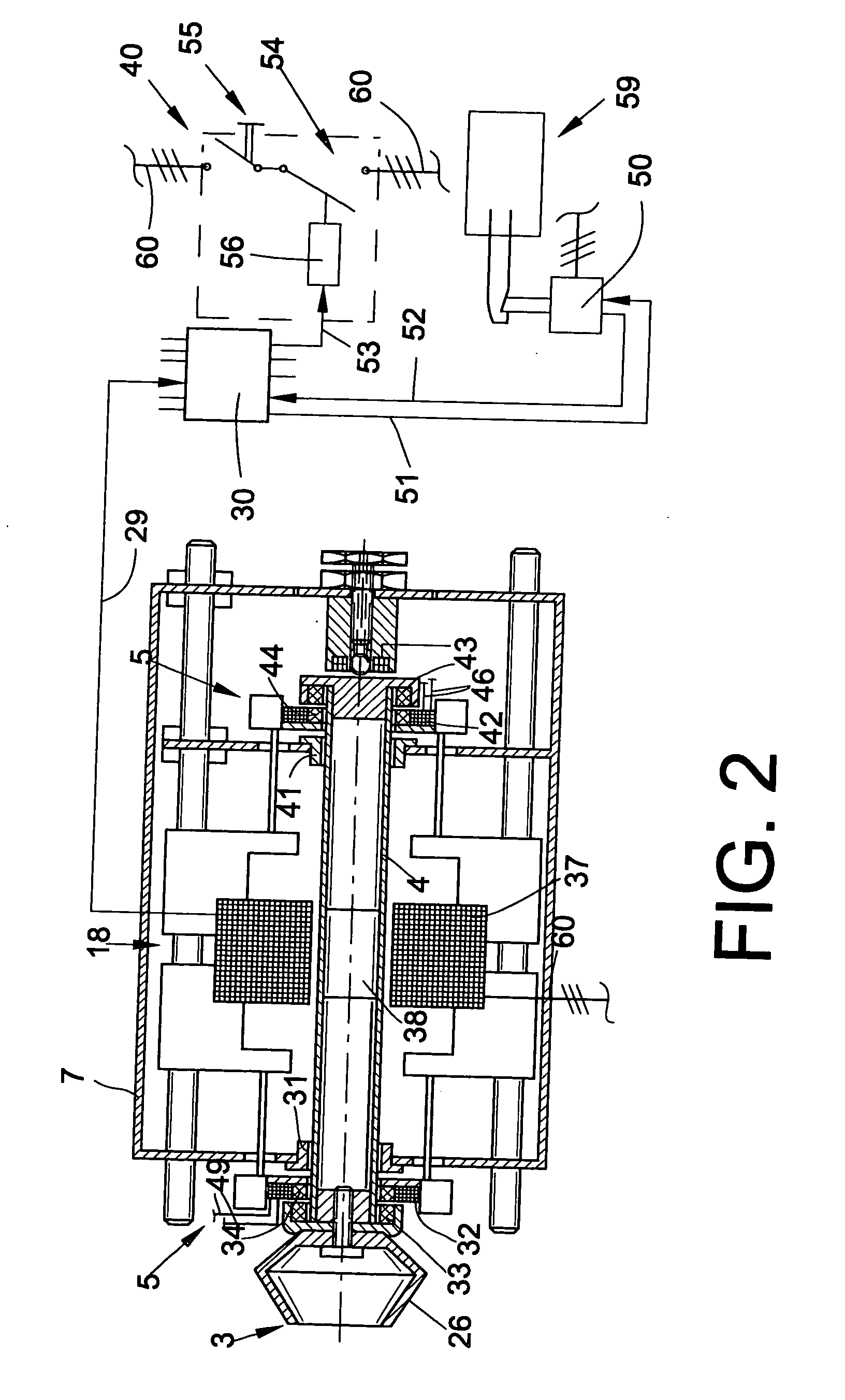
[0029] An open-end rotor spinning unit as shown in FIG. 1 is generally indicated by the numeral 1, and it comprises as usual a rotor housing 2, in which a spin cup 26 of a spinning rotor 3 rotates at a high speed. The spinning rotor 2 is driven by an individual electric motor drive, preferably a DC motor 18, and supported with its rotor shaft 4 in a magnetic bearing assembly 5.

[0030] In a known manner, the forwardly open rotor housing 2 is closed during the spinning process by a pivotally supported cover element 8, and it is connected via a corresponding suction line 10 to a source of vacuum 11 that generates a spinning vacuum as is needed in the rotor housing 2 for producing a yarn. As indicated, a recess of the cover element 8 accommodates a channel plate adapter 12, which comprises a yarn withdrawal nozzle 13 as well as the outlet region of a fiber feed channel 14. The yarn withdrawal nozzle 13 connects to a yarn withdrawal tube 15.

[0031] The cover element 8, which mounts in th...


PUM

PropertyMeasurementUnit
Angular velocityaaaaaaaaaa
Speedaaaaaaaaaa
Electric potential / voltageaaaaaaaaaa

Abstract

A method and an apparatus for operating an open-end spinning unit, which comprises a spinning rotor 1 that rotates during the spinning operation at a high rotational speed in a closed rotor housing 2. The spinning rotor is rotated by an individual electric motor drive 18 and supported in a smoothly running bearing assembly. When the drive is disconnected and the rotor housing is properly closed by a cover element 8, the spinning rotor is biased and rotated by an airflow resulting from a vacuum prevailing in the rotor housing and the motor drive operates as a generator. At least one of the electric quantities Pv, Gv which develop during the generator operation of the drive 18 is monitored, and upon exceeding a threshold value which can only be attained when the cover element is properly closed, a signal S is generated and processed in a control unit 30 to cause the cover element 8 on the rotor housing 2 to be locked, and thereafter the drive 18 of the spinning rotor 3 is released for a restart.

Description

BACKGROUND OF THE INVENTION [0001] The invention relates to a method for operating an open-end rotor yarn spinning unit, and an apparatus for carrying out the method. [0002] Different types of open-end rotor spinning units are known, which comprise a spinning rotor that rotates during the spinning process at a high rotational speed in a rotor housing which is closed by a cover element and kept under a vacuum. The open-end rotor spinning units differ both with respect to the bearing mount of their spinning rotors and with respect to their drive. [0003] The majority of the open-end spinning rotor units that are currently on the market and disclosed, for example, in DE 103 05 279 A1, and corresponding U.S. Publ. No. 2004 / 154280 comprise spinning rotors that are supported with their rotor shaft in the cusp of a so-called twin disk bearing. In the case of such twin disk bearings, it is common to provide for axially securing the spinning rotor, an additional thrust bearing, which may be c...

Claims


Application Information

Patent Timeline
IPC IPC(8): D01H4/00D01H4/08D01H4/12D01H4/14D01H4/42D01H13/20
CPCD01H4/08D01H13/20D01H4/42D01H4/14
Inventor WASSENHOVEN, HEINZ-GEORGCOENEN, NORBERT
Owner SAURER GERMANY GMBH & CO KG
Why Eureka
Try Eureka