Method to transfer fuel in a fuel system for a gas turbine engine

a gas turbine engine and fuel system technology, applied in the direction of turbine/propulsion fuel valves, machines/engines, mechanical equipment, etc., can solve the problems of shortening the life of injectors, affecting engine performance, and relatively complex systems

Inactive Publication Date: 2005-12-22
WOODWARD GOVERNOR CO
View PDF7 Cites 56 Cited by
  • Summary
  • Abstract
  • Description
  • Claims
  • Application Information

AI Technical Summary

Benefits of technology

[0012] The pressurizing and shutoff valve is also used for flow division between manifolds on engines that have more than one manifold and as a valve to open up a flow path from the manifold(s) to the suction port of an ejector pump. The ejector pump is supplied with flow from a port on the bypass valve. This flow is used during engine operation to operate a fuel tank ejector pump in the fuel tank. The checkvalve is located in the suction line or the inlet line of the ejector pump. The checkvalve prevents ejector leakage into the engine manifolds when the engine is shutdown.

Problems solved by technology

Coking of the residual fuel is a fire hazard and can lead to blockages in engine fuel injectors, which results in shorter injector life and can harm engine performance.
While the Dalton patent provides a unique system for pumping the residual fuel from an engine manifold after the engine is shut down, it is a relatively complex system.
These features add to the overall complexity and may decrease the reliability of the system.

Method used


Image

  • Method to transfer fuel in a fuel system for a gas turbine engine
  • Method to transfer fuel in a fuel system for a gas turbine engine
  • Method to transfer fuel in a fuel system for a gas turbine engine

Examples


Embodiment Construction

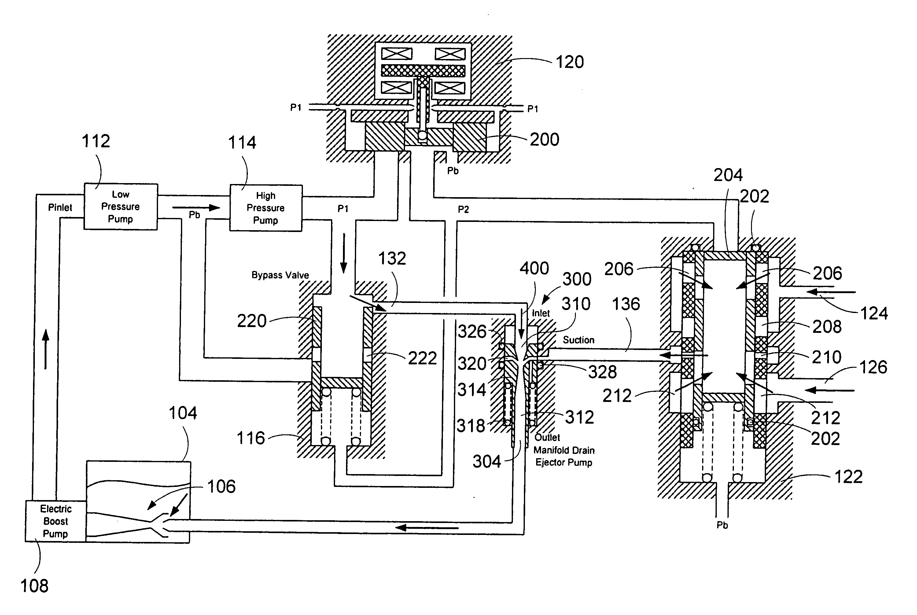
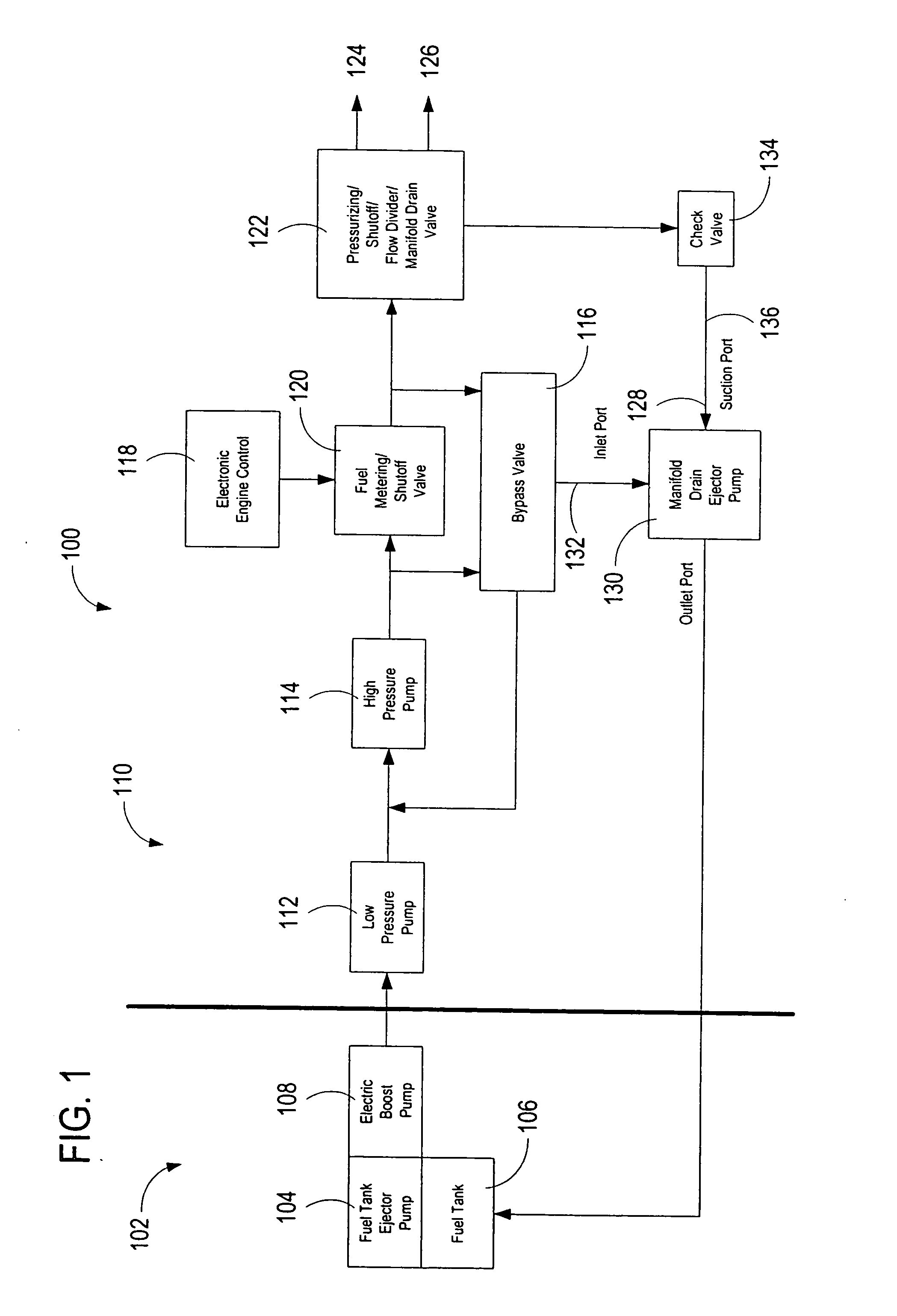
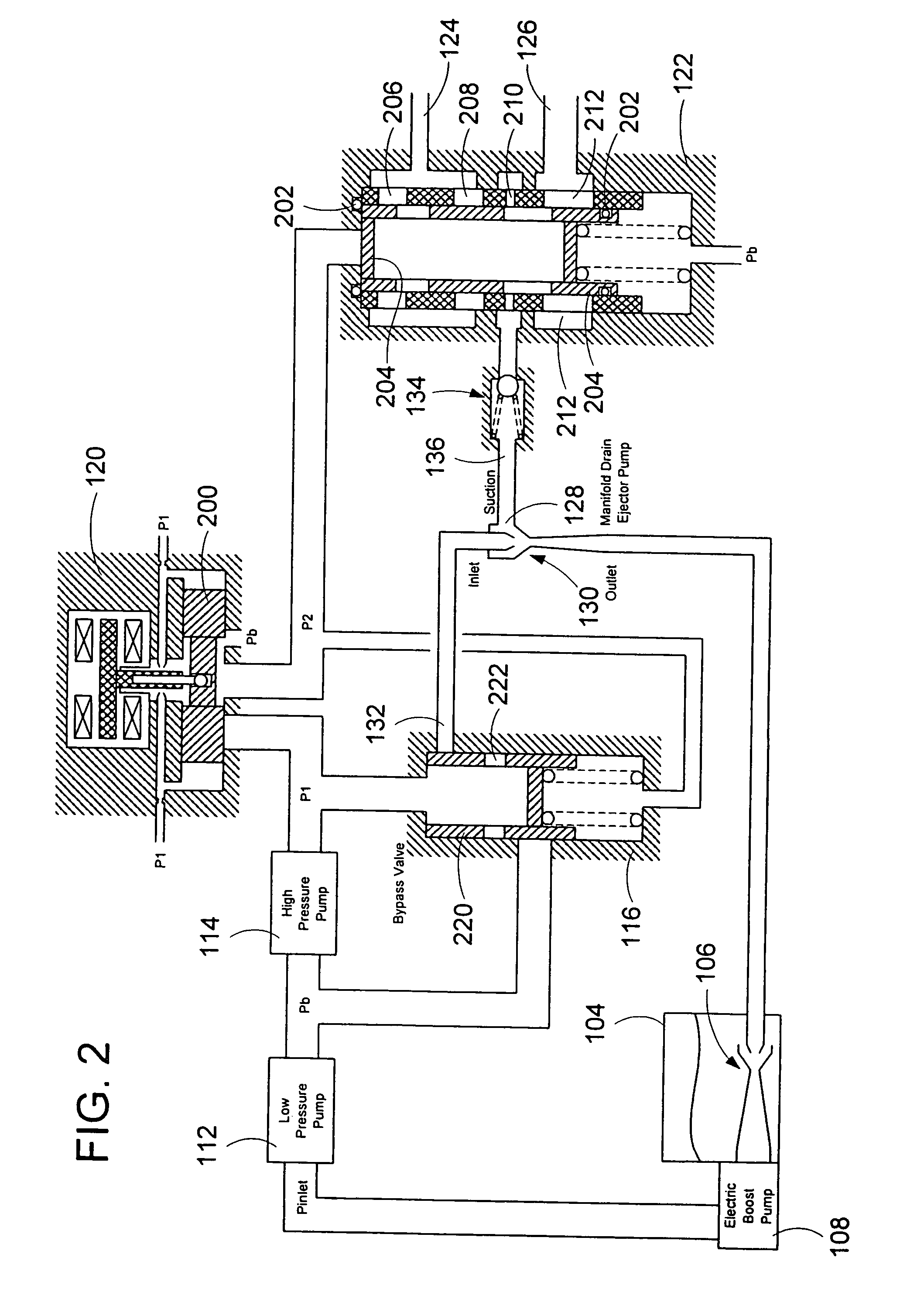
[0030] The invention provides a system for automatically transferring the fuel from one or more engine fuel manifolds directly to the engine fuel tank(s) during engine shutdown using an ejector pump. The system will be described in relation to an aircraft fuel system. While the system will be described in such a fuel system, it is recognized that the system may be used in other types of gas turbine engine applications. The system requires fewer components than other systems. In addition to the fuel ejector, one additional component is used. This component is a simple, inexpensive checkvalve that may be integrated with the ejector pump. In the system, “motive flow,” which is commonly used to supply the fuel tank ejector pump, is also used for the manifold drain ejector pump inlet flow. A metering valve initiates fuel flow shutoff and is used in the draining of the fuel manifolds. This eliminates the need for an additional solenoid dedicated to the shutoff function that is required in...


PUM


Abstract

A system for automatically transferring the fuel from one or more engine fuel manifolds directly to the engine fuel tank(s) during engine shutdown using an ejector pump has been presented. A checkvalve, which may be integrated with the ejector pump, is also used. A metering valve initiates fuel flow shutoff and is used in the draining of the fuel manifolds, thereby eliminating the need for an additional solenoid dedicated mainly to the shutoff function. The shutoff and pressurizing valve provides flow division between manifolds and manifold drain for systems having multiple manifolds. The bypass valve is used to turn the motive flow and/or manifold drain functions on and off as a function of engine speed at start and shutdown.

Description

CROSS-REFERENCE TO RELATED PATENT APPLICATIONS [0001] This patent application is a divisional of co-pending U.S. patent application Ser. No. 10 / 461,205, filed Jun. 13, 2003.FIELD OF THE INVENTION [0002] This invention pertains to gas turbine engines, and more particularly to a system for transferring fuel from the engine manifolds of a gas turbine engine at engine shut down. BACKGROUND OF THE INVENTION [0003] In many gas turbine engines, the fuel system for regulating the flow of fuel to the combustion chamber consists of one or more fuel nozzles arranged in the combustion chamber, a fuel pump for pressurizing fuel from the fuel supply, a fuel metering unit for controlling the flow of fuel to the fuel nozzles and one or more fuel manifolds fluidically connecting the fuel metering unit to the fuel nozzles. [0004] During engine start-up, fuel is pumped from the fuel supply to the fuel metering unit by the fuel pump and, once a sufficient start-up pressure is attained, the pressurizing...

Claims


Application Information

Patent Timeline
Patent Type & Authority Applications(United States)
IPC IPC(8): F02C7/232F02C7/236F02C9/38F02G3/00
CPCF02C7/232F02C9/38F02C7/236
Inventor BARYSHNIKOV, DMITRIYSMITH, DOUGLAS P.
Owner WOODWARD GOVERNOR CO
Why Eureka
Try Eureka