
Device for performing measurements and/or taking samples in molten metals

Active Publication Date: 2005-12-22
HERALUS ELECTRO NITE INT NV
View PDF12 Cites 6 Cited by
  • Summary
  • Abstract
  • Description
  • Claims
  • Application Information

AI Technical Summary

Benefits of technology

[0006] The problem is solved for the invention characterized above in that on the lance holder a contact piece is arranged for making contact with signal lines of the immersion probe, furthermore in that the sublance body is movably connected to the lance holder or to a part thereof and / or in that the lance holder has several parts relatively movable to each other, whereby the contact piece is arranged to be movable relative to the sublance. The sublance is pushed tight onto the upper part of the lance holder and is preferably held so that it cannot move. The lower part of the lance holder is movable with the contact piece, so that the probe can be brought into contact with the contact piece. The lance holding can thereby adapt to the already set sensor, so that a sufficient contact is possible even for slightly deformed components or even when molten metal adheres to the sublance.
[0007] Different insertion depths of the sublance into the carrier tube of the immersion probe are likewise compensated in this manner. Preferably, the sublance body with the lance holder and / or the parts of the lance holder are arranged to be movable in the axial direction and / or in the radial direction. Furthermore, it is advantageous when the axial movement and the radial movement are realized by pairs of connection parts that are different from each other, in order to obtain the highest possible flexibility and adaptability. Especially for adhesion of molten metal on the sublance or for differently arranged contact parts of the immersion probe, an axial movement is important, in order to guarantee the correct contact with the immersion probe. In particular, it is advantageous when the movement is realized by elastic parts arranged between rigid parts, wherein the elastic parts can be formed as a spring, for example as a coil spring, or as an elastic ring.
[0008] Furthermore, it is useful if a part of the lance holder has a receiving hole, in which a peg of a second part of the lance holder can move in the axial direction, wherein a coil spring is arranged between the first and the second parts of the lance holder. For this purpose, it is advantageous if the coil spring is arranged between a stopping surface arranged at the front end or on the peripheral surface of the peg and a second stopping surface is arranged at or in the hole. The components guaranteeing the movement are thereby protected themselves.

Problems solved by technology

In practice, however, it has been shown that, due to the loads exerted on a sublance during use, these sublances become slightly deformed, so that the lance holder can no longer be placed exactly over an immersion probe and the probe cannot be received without problems.
In particular, the contact part housed in the carrier tube cannot always be reached at the same depth by the counter contact in the sublance.
As a result, splashes of the molten metal frequently settle onto parts of the sublance, which must remain free for forming the contact, so that trouble-free placement of the immersion probes is impossible.
This can disrupt the entire steel making process.

Method used


Image

  • Device for performing measurements and/or taking samples in molten metals
  • Device for performing measurements and/or taking samples in molten metals
  • Device for performing measurements and/or taking samples in molten metals

Examples


Embodiment Construction

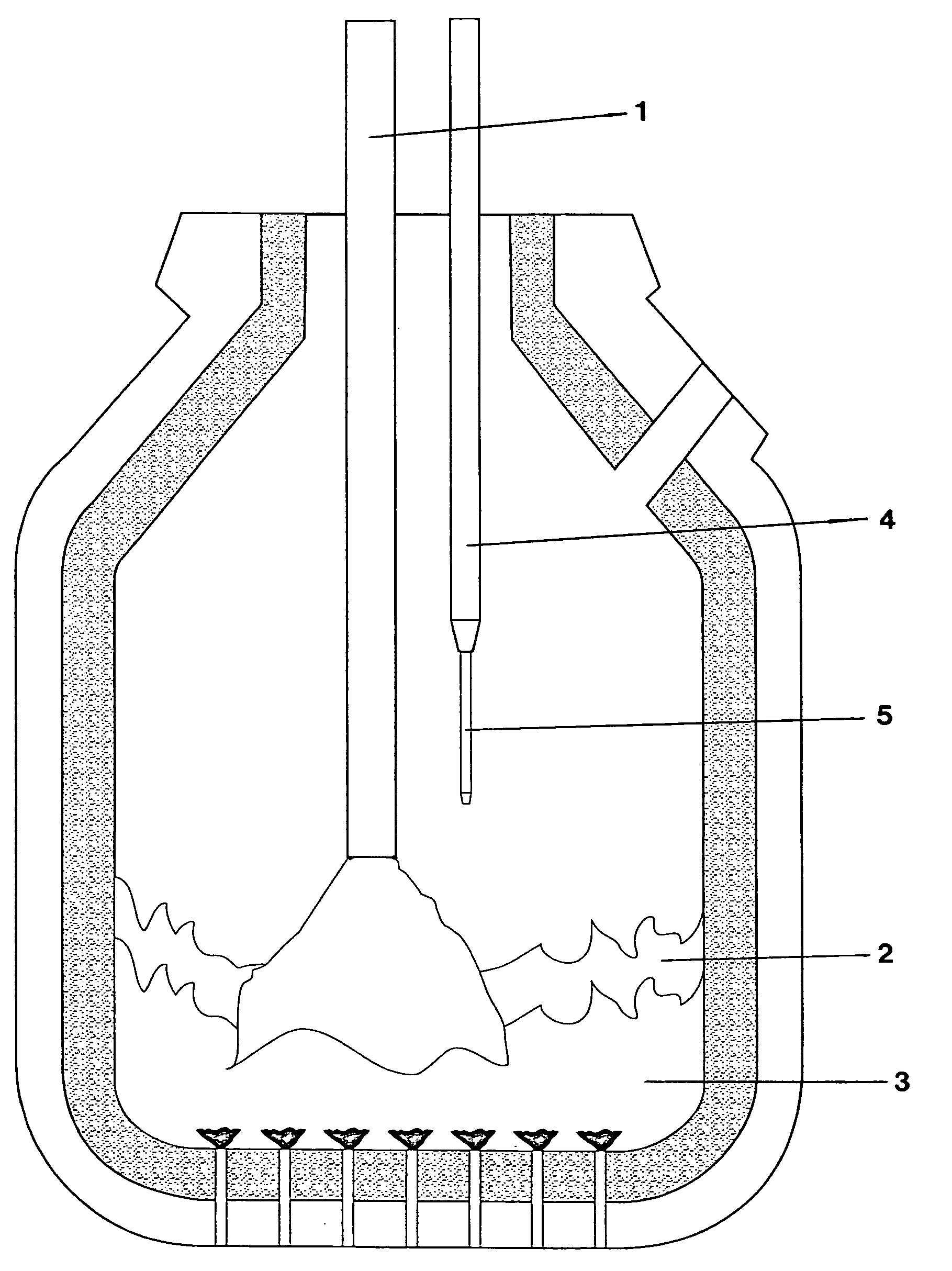
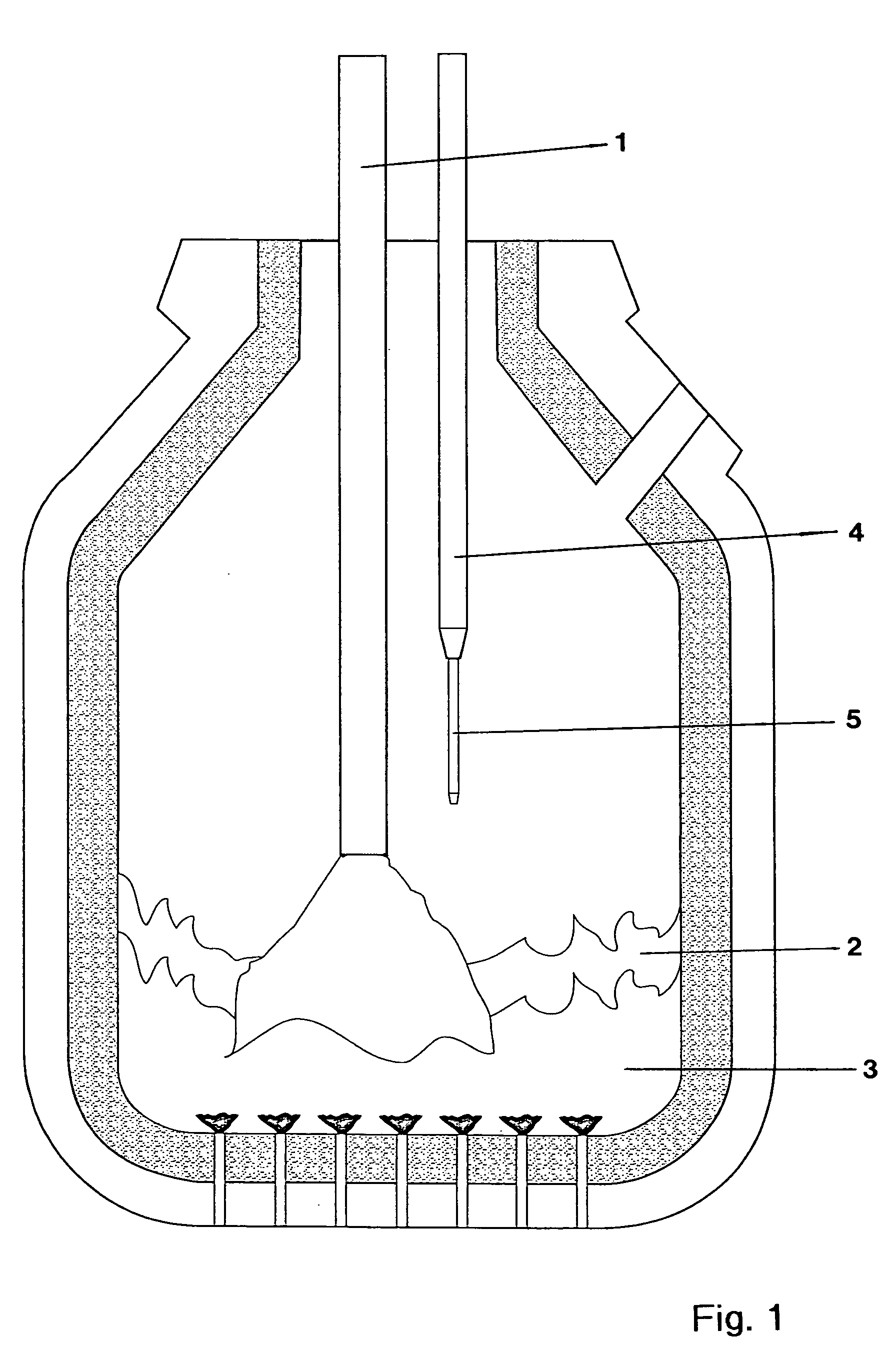
[0014] In the converter furnace shown in FIG. 1 a blowing lance 1 is arranged, which blows oxygen into the molten slag 2 or molten steel 3. Next to this lance a sublance 4 with an immersion probe 5 is arranged. The sublance 4 travels from above into the converter furnace until the immersion probe 5 is immersed in the molten steel 3. After the measurement, the sublance is pulled up; the immersion probe 5 is destroyed.

[0015] If the probe is designed as a measurement probe, then the measurement is performed during the immersion in the molten steel 3. A sample chamber arranged in the immersion probe 5 was filled while in the molten steel 3. The sample chamber is removed from the discarded immersion probe 5, and the sample can be analyzed. For the next measurement, another immersion probe 5 is taken from a storage container, usually mechanically mounted on the sublance 4, and inserted into the converter furnace for the measurement.

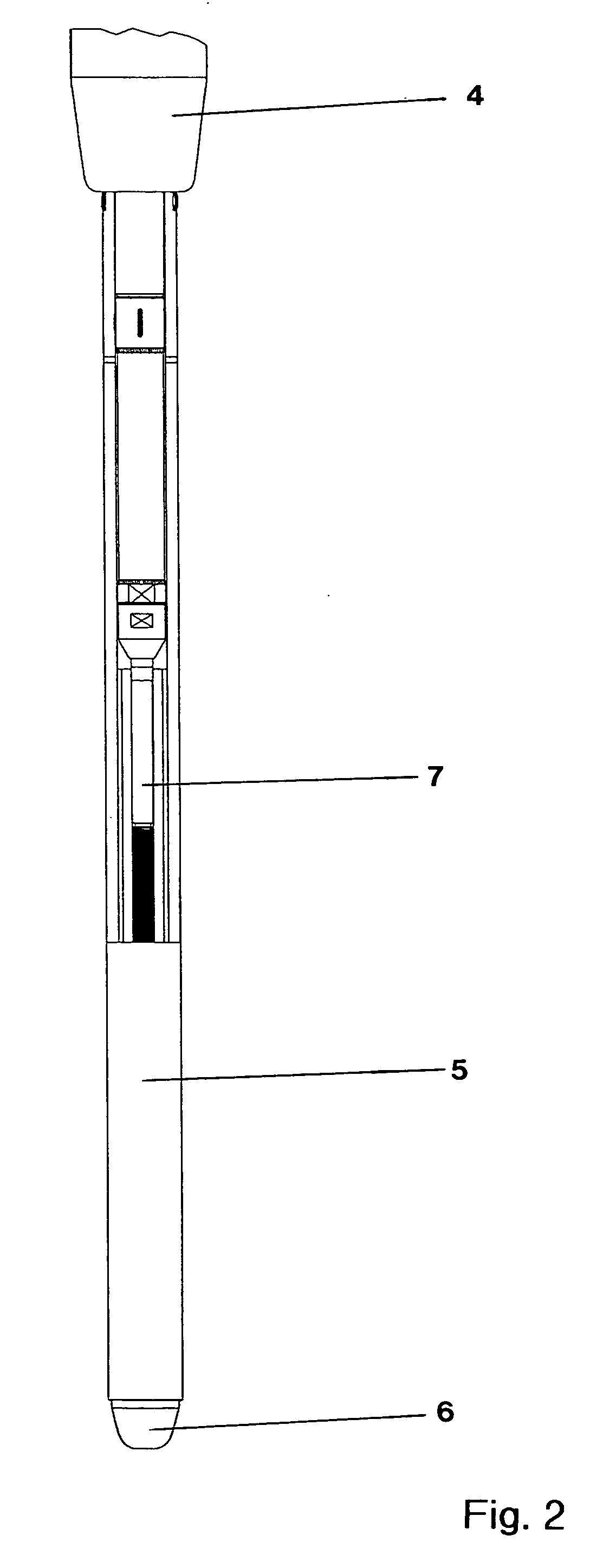
[0016]FIG. 2 shows the immersion probe 5 arranged at th...


PUM

PropertyMeasurementUnit
Elasticityaaaaaaaaaa

Abstract

A device is provided for performing measurements and / or taking samples in molten metals with a sublance, which has a sublance body, on whose one end a lance holder is arranged for receiving an immersion probe. The sublance body is movably connected to the lance holder and / or the lance holder has several parts relatively movable to each other.

Description

BACKGROUND OF THE INVENTION [0001] The invention relates to a device for performing measurements and / or taking samples in molten metals with a sublance, which has a sublance body, on whose one end a lance holder is arranged for receiving an immersion probe. [0002] Such devices are sufficiently well known to those skilled in the art. They are used for measurements or taking samples in molten metals. Such sampling is partially automated, wherein a sublance is dipped into a melt container, after which the immersion probe arranged on the sublance is discarded, because it is used up, and a new immersion probe is placed on the sublance. In order to automate this procedure, the sublance must be able to be positioned exactly over a probe storage container. [0003] In practice, however, it has been shown that, due to the loads exerted on a sublance during use, these sublances become slightly deformed, so that the lance holder can no longer be placed exactly over an immersion probe and the pro...

Claims


Application Information

Patent Timeline
IPC IPC(8): C21C5/46F27B3/28F27D19/00F27D21/00G01K13/12G01N1/10G01N1/12G01N33/00G01N33/20
CPCC21C5/4606C21C5/4673F27B3/28F27D19/00G01N1/125F27D2019/0003F27D2019/0006G01K13/125F27D21/0014G01N33/205C21B7/24
Inventor NEYENS, GUIDO JACOBUSBELL, SHAUN ANDREW
Owner HERALUS ELECTRO NITE INT NV
Features
  • Generate Ideas
  • Intellectual Property
  • Life Sciences
  • Materials
  • Tech Scout
  • Unparalleled Data Quality
  • Higher Quality Content
  • 60% Fewer Hallucinations
Learn More