Buoyant water chlorinator housing

a technology of buoyant water and chlorinator, which is applied in the direction of water cleaning, other chemical processes, separation processes, etc., can solve the problems of inconvenience for users, inconvenience for users, and inconvenience of known chlorinator units

Inactive Publication Date: 2005-12-22
LIN FONG JEI
View PDF2 Cites 27 Cited by
  • Summary
  • Abstract
  • Description
  • Claims
  • Application Information

AI Technical Summary

Benefits of technology

[0011] The invention comprises an improved water chlorinator housing which eliminates the inconveniences noted above and which provides buffer solution receptacles and sensor electrode suspension elements for facilitating handling of the

Problems solved by technology

While the above-described chlorinator unit is convenient to use and provides accurate readings of the water temperature, pH level and oxidation reduction potential (ORP), the need for a buffer solution during the pH in situ calibration process makes the calibration step somewhat inconvenient for the user.
This is inconvenient for the user.
Another inconvenience with the k

Method used


Image

  • Buoyant water chlorinator housing
  • Buoyant water chlorinator housing
  • Buoyant water chlorinator housing

Examples


Embodiment Construction

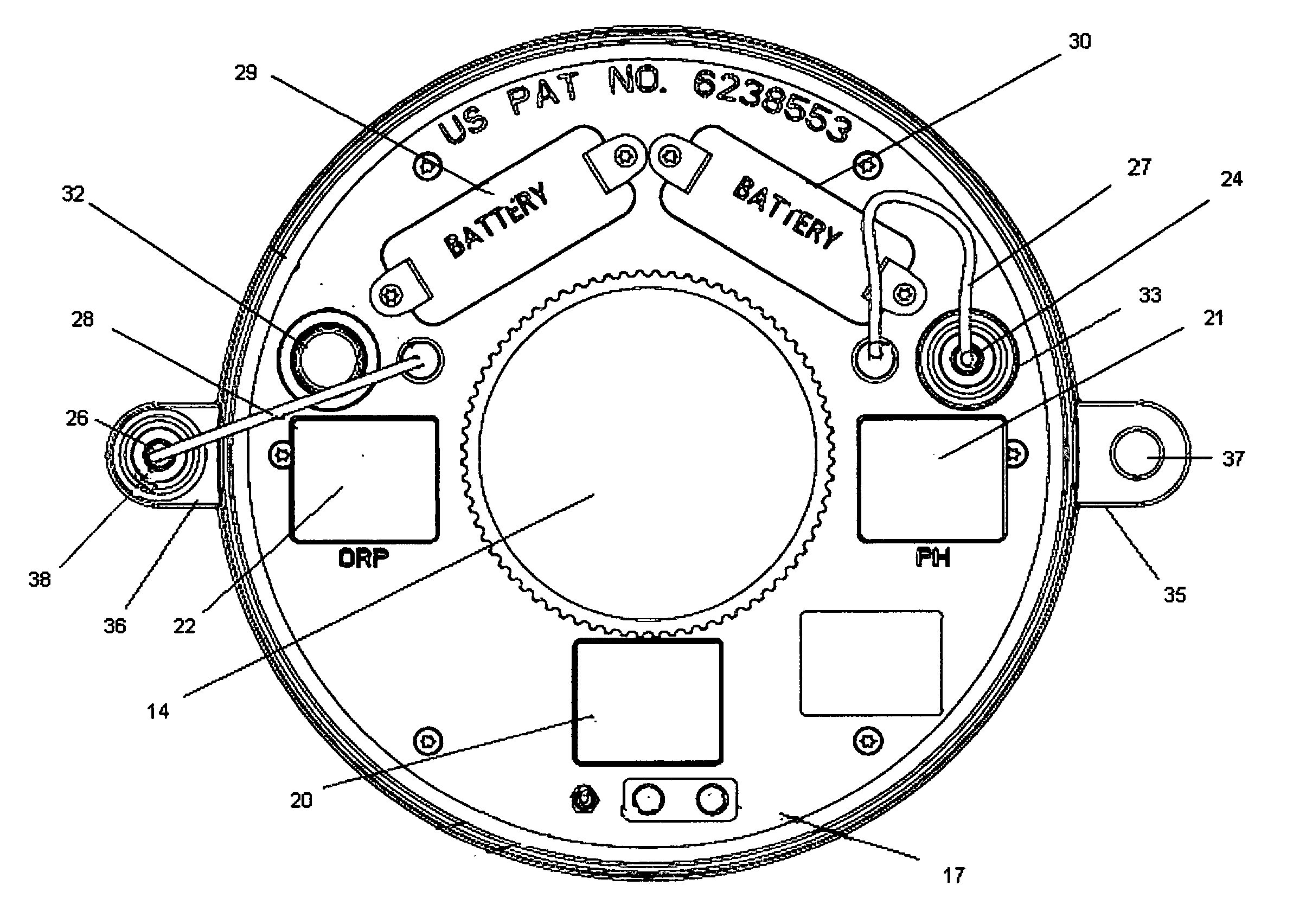
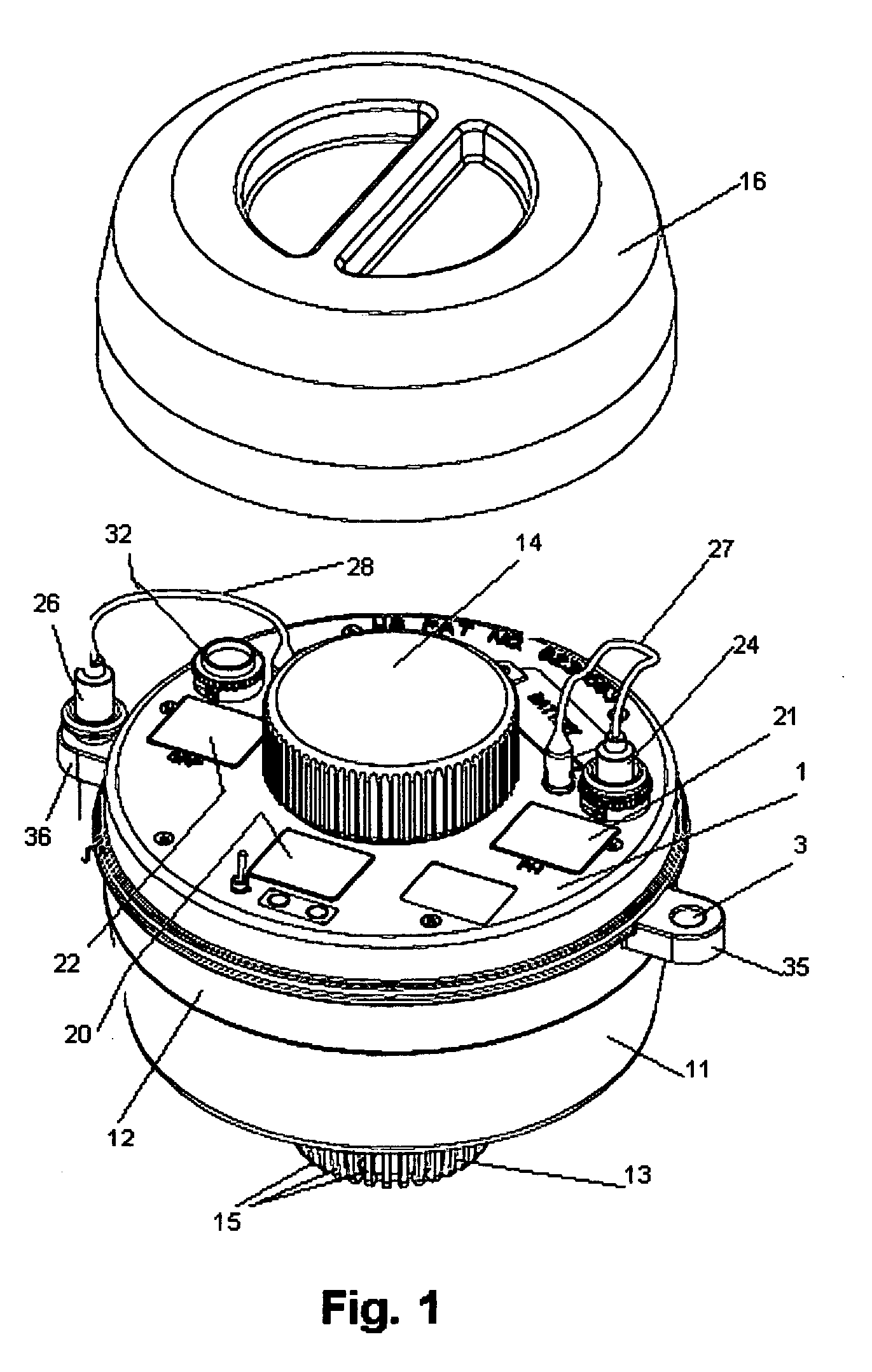
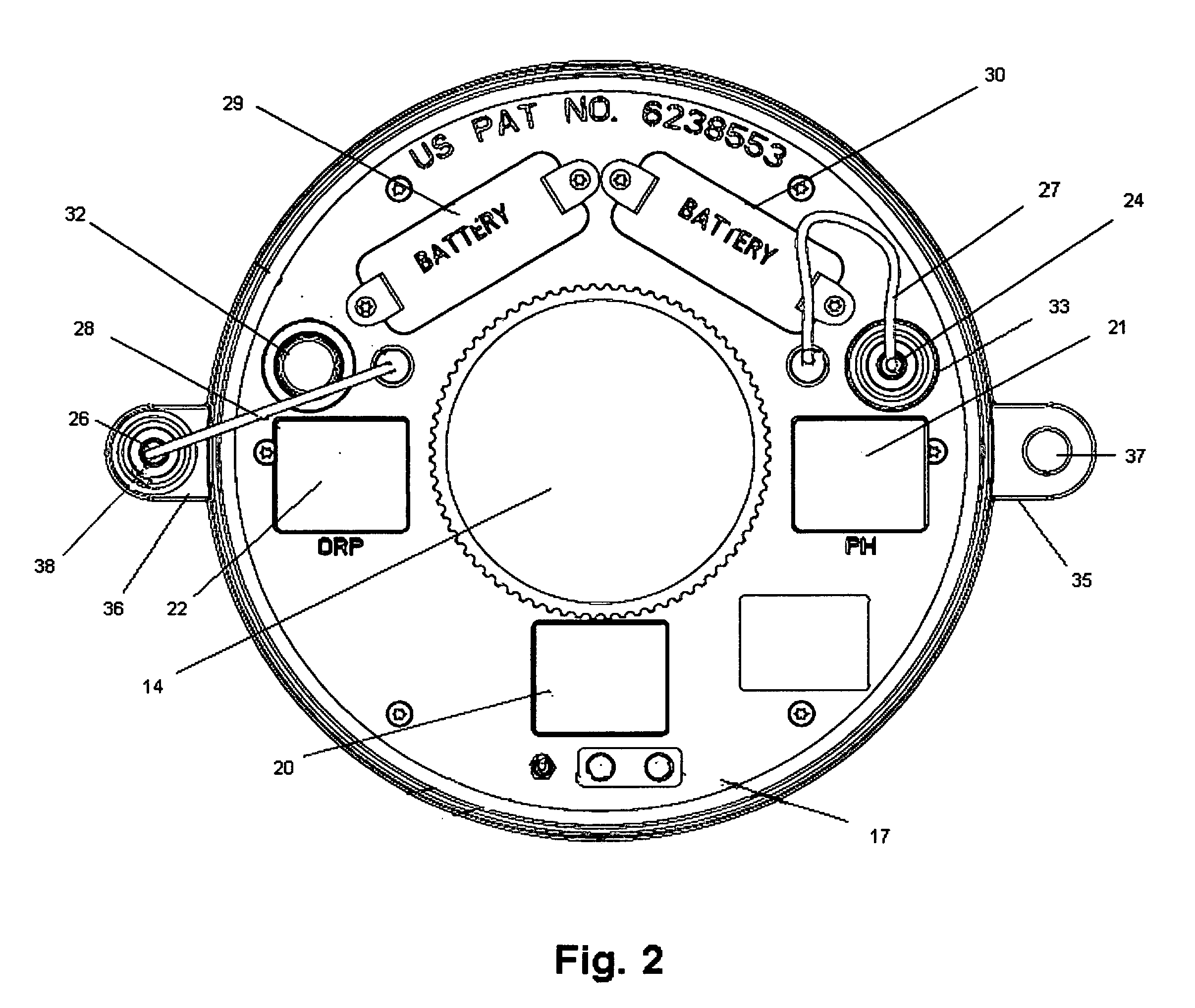
[0025] Turning now to the drawings, FIG. 1 is a schematic view illustrating the preferred embodiment of the invention. As seen in this FIG., the preferred embodiment includes a housing 11, typically made from plastic material. Housing 11 has an upper sealed hollow space 12 to ensure buoyancy in water, and a lower wall portion 13 providing a hollow interior for receiving one or more water-soluble chlorine tablets (not shown). A chlorine chamber cover 14 is removably mounted in the central region of the top of housing 11 to provide access to the hollow interior. A plurality of openings 15 are distributed about the circumference of lower wall portion 13 to allow water to enter the hollow interior volume and leach chlorine from the tablets. A protective cover 16 is removably mounted to the top of housing 11. To add more chlorine tablets, covers 16 are 14 are sequentially removed to expose the hollow lower interior.

[0026] Arranged about the upper peripheral surface 17 of housing 11 are ...


PUM

PropertyMeasurementUnit
Temperatureaaaaaaaaaa

Abstract

A buoyant water chlorinator unit has a housing with an upper surface and an apertured chamber for receiving a chlorination agent. Three separate measurement systems are carried by the housing: a water temperature system, a pH level system, and an oxidation reduction system. The housing has apertures in the upper surface which receive removable sensor electrode receptacles capable of removably receiving the sensor electrodes for storage and containing a buffer solution used for calibration and sensor electrode preservation purposes. Outwardly extending suspension elements formed in the upper region of the housing enable sensor electrodes to be suspended from the housing with their lower ends immersed in water.

Description

CROSS-REFERENCE TO RELATED PATENT AND APPLICATION [0001] This invention is an improvement over the inventions disclosed and claimed in commonly-owned U.S. Pat. No. 6,238,553 issued May 29, 2001 for “Buoyant Water Chlorinator With Temperature, pH measurement, and Chlorine Concentration Displays”; commonly-owned pending U.S. patent application Ser. No. 10 / 792,303 filed Mar. 3, 2004 for “pH Measurement System For Buoyant Water Chlorinator”; and commonly-owned pending U.S. patent application Ser. No. 10 / 352,608 filed Jan. 27, 2003 for “Improved Buoyant Water Chlorinator With Range Indicators For Temperature, pH Measurement And Chlorine Concentration”, the disclosures of which are hereby incorporated by reference.BACKGROUND OF THE INVENTION [0002] This invention relates generally to water chlorination units of the type used in pools and spas. More particularly, this invention relates to an improved buoyant water chlorination housing design. [0003] Water chlorination units are known which...

Claims


Application Information

Patent Timeline
IPC IPC(8): B01D17/12
CPCC02F1/688C02F1/76C02F2103/42C02F2209/005E04H4/1281C02F2209/04C02F2209/06C02F2303/04C02F2209/02
Inventor LIN, FONG-JEI
Owner LIN FONG JEI
Why Eureka
Try Eureka