Light emitting apparatus generating white light by mixing of light of a plurality of oscillation wavelengths

Active Publication Date: 2005-12-22
SHARP KK
View PDF10 Cites 37 Cited by
  • Summary
  • Abstract
  • Description
  • Claims
  • Application Information

AI Technical Summary

Benefits of technology

[0023] An object of the present invention is to provide a light emitting apparatus which does not require independent adjustment means of the same n

Problems solved by technology

With either method, however, it is difficult to actually obtain desired chromaticity and intensity of emitted light.
Furthermore, once the white light source using the fluorescent material is manufactured as a product, adjustment of the chromaticity becomes substantially impossible.
When a plurality of white light sources are aligned to be used as a backlight of a liquid crystal display device or a light source for illu

Method used


Image

  • Light emitting apparatus generating white light by mixing of light of a plurality of oscillation wavelengths
  • Light emitting apparatus generating white light by mixing of light of a plurality of oscillation wavelengths
  • Light emitting apparatus generating white light by mixing of light of a plurality of oscillation wavelengths

Examples


first embodiment

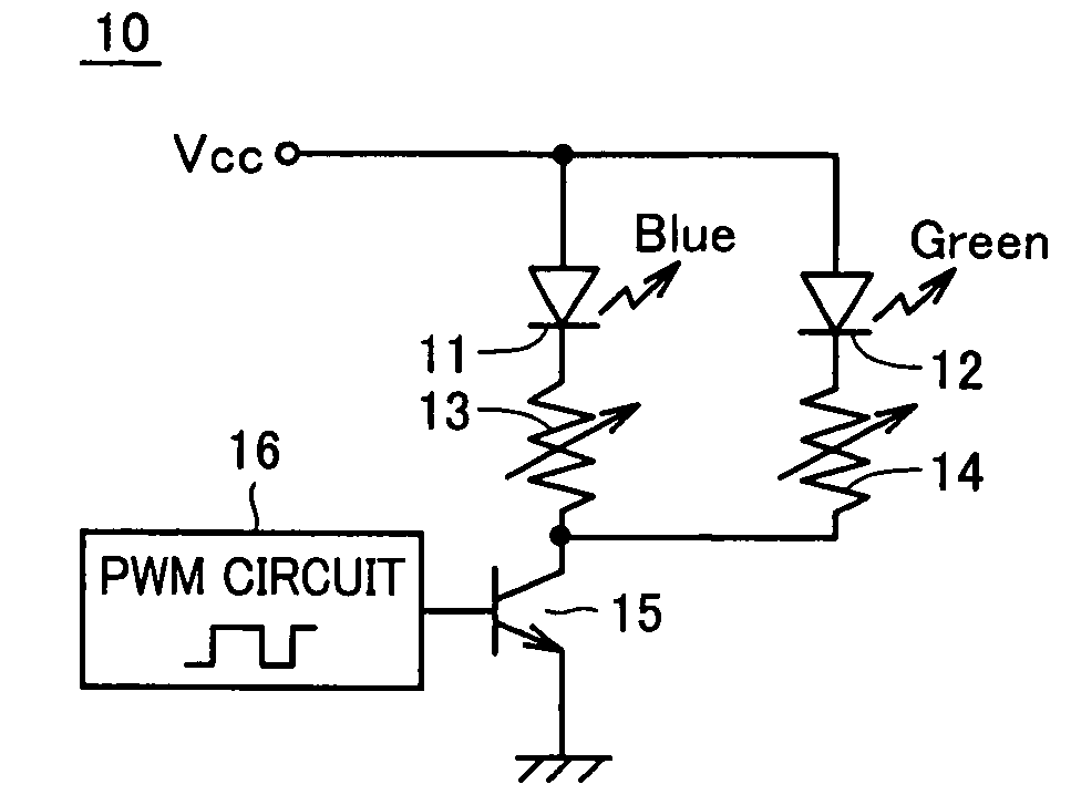
[0060] Referring to FIG. 1, a light emitting apparatus 10 of a first embodiment includes a blue light emitting diode 11, a green light emitting diode 12, variable resistances 13, 14, a transistor 15, and a PWM circuit 16. Blue light emitting diode 11, variable resistance 13 and transistor 15 are connected in series between a power supply node Vcc and a ground node. Green light emitting diode 12 and variable resistance 14 are connected in series between power supply node Vcc and a collector of transistor 15. PWM circuit 16 is connected to a base of transistor 15 and applies a driving voltage having a modulated pulse width to the base.

[0061] Transistor 15 is turned ON / OFF corresponding to the HIGH level / LOW level of the driving voltage applied by PWM circuit 16. Therefore, a lighting time of blue light emitting diode 11 and green light emitting diode 12 can be controlled by adjusting the pulse width of the driving voltage applied from PWM circuit 16.

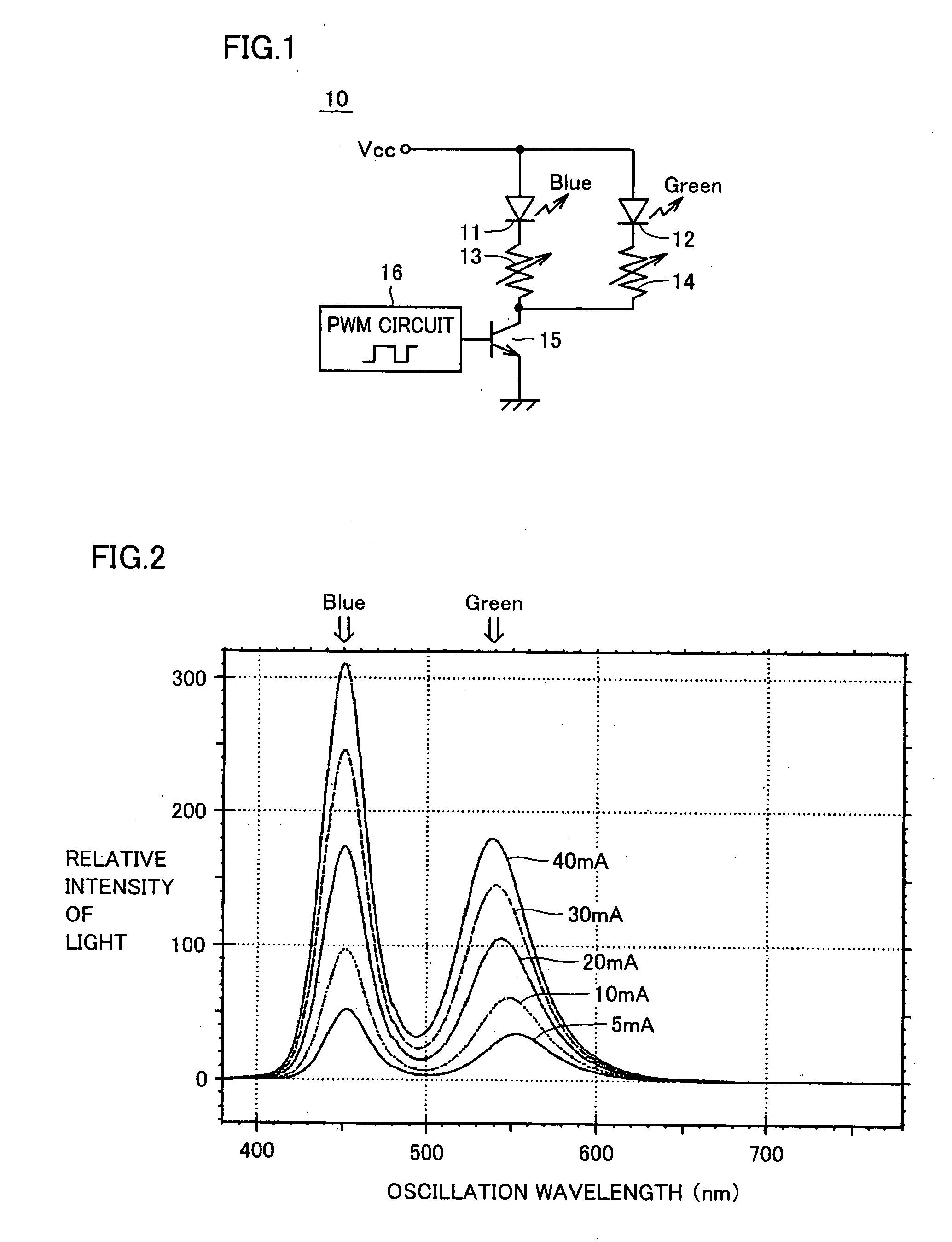
[0062]FIG. 2 is a graph of variat...

second embodiment

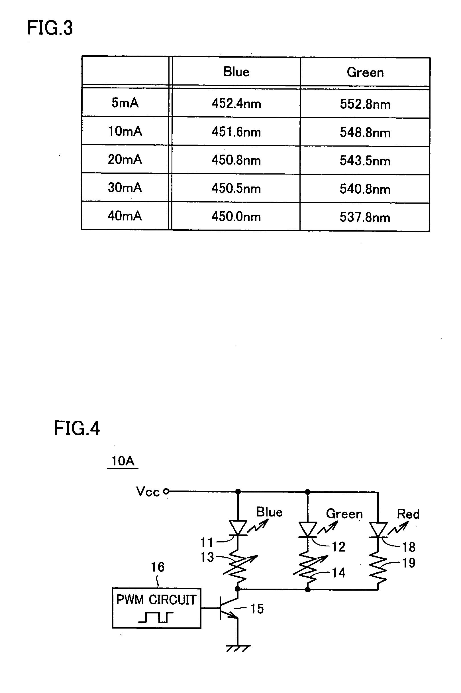
[0076] In each of light emitting apparatuses 10 and 10A of the first embodiment, blue light emitting diode 11 having a small variation in wavelength for a variation in current amount is connected in parallel to green light emitting diode 12 having a large variation in wavelength for a variation in current amount. Therefore, respective variable resistances 13, 14 are required for blue light emitting diode 11 and green light emitting diode 12.

[0077] Though providing of individual variable resistances 13, 14 has an advantage such that the amount of the current flowing through each of blue light emitting diode 11 and green light emitting diode 12 can be individually set beforehand, it requires an adjustment operation for each variable resistance and, furthermore, an area of a circuit increases according to a number of variable resistances. Therefore, in a second embodiment, light emitting apparatuses 20 and 20A which overcame such problems are described in detail.

[0078] Referring to F...

third embodiment

[0086] In each of light emitting apparatuses 10, 20 of the first and second embodiments, blue light emitting diode 11 having a small variation in wavelength for a variation in current amount is combined with green light emitting diode 12 having a large variation in wavelength for a variation in current amount.

[0087] Though use of blue light emitting diode 11 and green light emitting diode 12 separately is advantageous in terms of cost because each diode is generally inexpensive, an area of a circuit increases according to a number of light emitting diodes. Therefore, in a third embodiment, light emitting apparatuses 30 and 30A which overcame such problem are described in detail.

[0088] Referring to FIG. 7, light emitting apparatus 30 of the third embodiment includes a light emitting diode 31 oscillating a plurality of wavelengths, variable resistance 13, transistor 15, and PWM circuit 16. Light emitting diode 31 oscillating a plurality of wavelengths, variable resistance 13 and tra...


PUM


Abstract

A current of the same amount or in a constant ratio is applied to each of a combination of a blue light emitting diode having a small wavelength variation and a green light emitting diode having a large wavelength variation. With this, as an amount of applied current increases, an oscillation wavelength of the green light emitting diode having the large wavelength variation changes from a long wavelength side to a short wavelength side and mixes with a blue color of the blue light emitting diode having the small wavelength variation to gradually change chromaticity as a whole. When desired chromaticity is obtained, the amount of the current is fixed.

Description

[0001] This nonprovisional application is based on Japanese Patent Application No. 2004-182712 filed with the Japan Patent Office on Jun. 21, 2004, the entire contents of which are hereby incorporated by reference. BACKGROUND OF THE INVENTION [0002] 1. Field of the Invention [0003] The present invention relates to a light emitting apparatus and, more specifically, to a light emitting apparatus generating white light by mixing of light of a plurality of oscillation wavelengths. [0004] 2. Description of the Background Art [0005] Studies have been made to develop a white light source of high quality using a light emitting diode (also referred to as an LED). The white light source using a light emitting diode is utilized in, for example, a backlight of a liquid crystal display device, a luminaire or an image reading apparatus. [0006] Methods of generating a white light source with a light emitting diode are broadly divided into a method using a fluorescent material and a method using a ...

Claims


Application Information

Patent Timeline
IPC IPC(8): G05F1/00H01L33/00H05B37/02H05B44/00
CPCH05B33/0818H05B33/0869H05B33/0821H05B45/22H05B45/40
Inventor CHIKUGAWA, HIROSHIKATOH, MASAAKI
Owner SHARP KK
Why Eureka
Try Eureka