Liquid crystal display device, image display device and manufacturing method thereof

a liquid crystal display device and image display technology, applied in non-linear optics, instruments, optics, etc., can solve the problems of unable to feed the required charge, difficult rapid driving of the liquid crystal display device, and remarkably increased voltage drop, etc., to achieve rapid driving, reduce the resistance of feeding electrodes, and high brightness

Inactive Publication Date: 2005-12-22
PANASONIC LIQUID CRYSTAL DISPLAY CO LTD +1
View PDF35 Cites 7 Cited by
  • Summary
  • Abstract
  • Description
  • Claims
  • Application Information

AI Technical Summary

Benefits of technology

[0013] Accordingly, it is an object of the present invention to provide an active matrix liquid crystal display device which can reduce resistance of feeding electrodes which constitute holding capacities. It is another object of the present invention to provide a rapid driving active matrix type liquid crystal display device having high brightness by obviating the reduction of numerical aperture of pixels.
[0158] Due to the above-mentioned constitution (64) or (65), even when the through holes are formed insufficiently, the feeding of electricity is performed through the connection lines from the neighboring pixel sides. Further, when the through holes which connect each counter electrode with each reference electrode are formed in a plural number for every pixel, the reliability of connection of the electrode layers can be enhanced. (66):

Problems solved by technology

Further, corresponding to the increase of the distance between the electrode and a feeding end, the voltage drop is remarkably increased so that there arises a case that the required charge cannot be fed.
As a result, this has been one of causes which make the rapid driving of liquid crystal display device difficult.
Further, along with the demand for high definition, the size of pixels per one pixel is reduced so that there has been a task that it is difficult to form the sufficient holding capacity.
Further, although it is effective to reduce the size of the holding capacity to enhance the numerical aperture, this brings about the reduction of the holding capacity.

Method used


Image

  • Liquid crystal display device, image display device and manufacturing method thereof
  • Liquid crystal display device, image display device and manufacturing method thereof
  • Liquid crystal display device, image display device and manufacturing method thereof

Examples


first embodiment

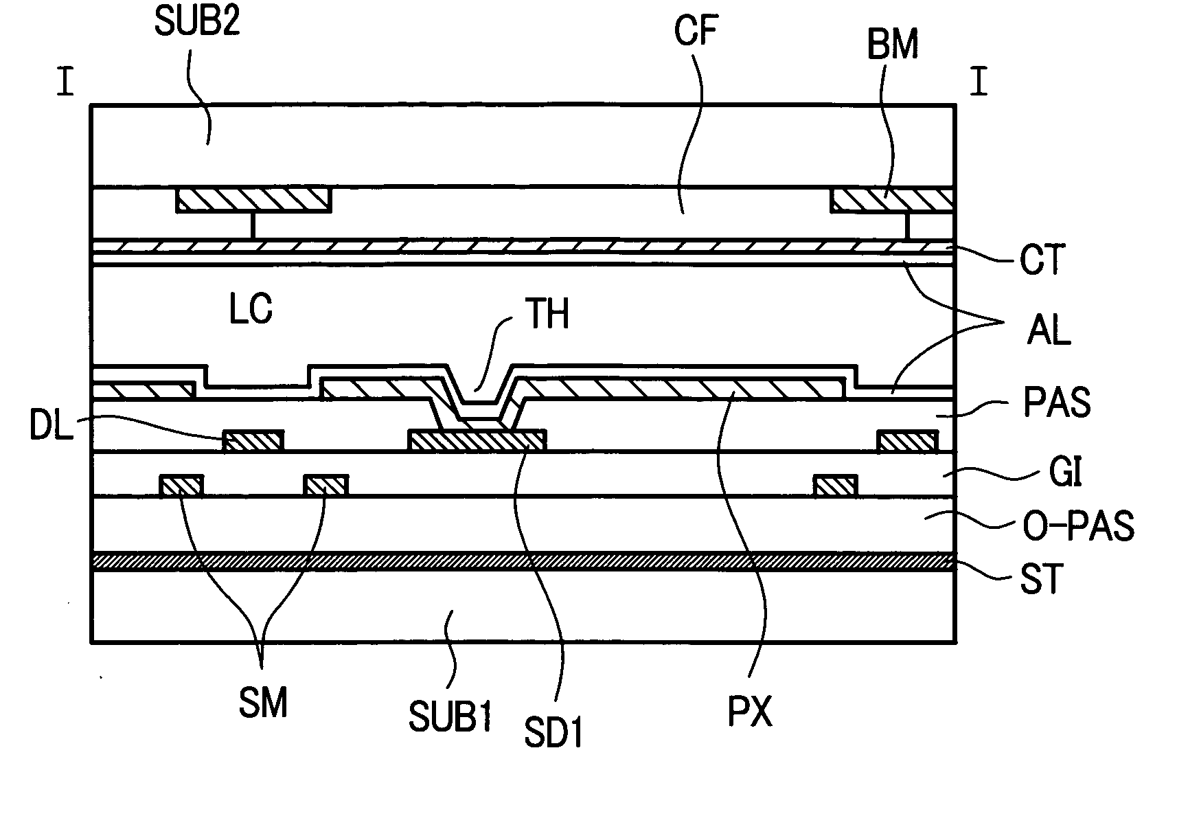
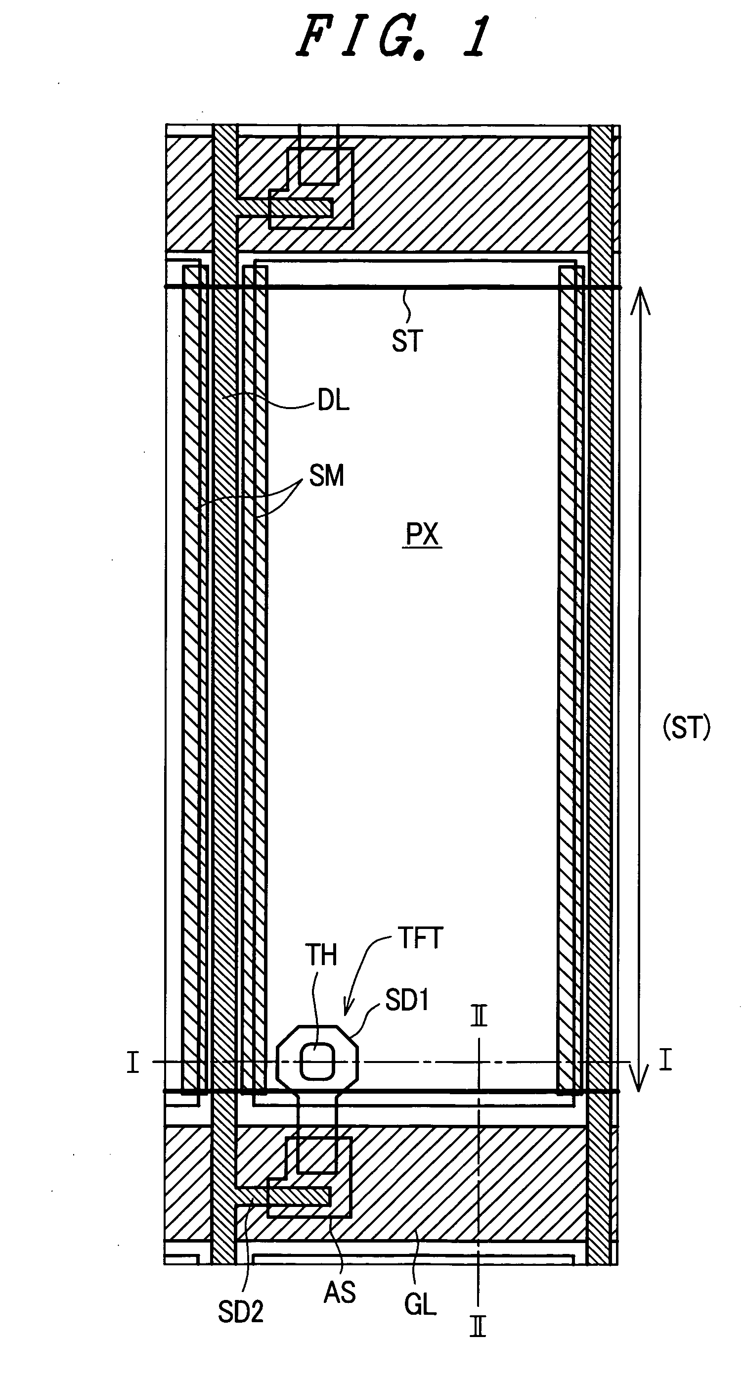
[0305]FIG. 1 is a plan view of the vicinity of one pixel of a vertical field type liquid crystal display device for schematically explaining the pixel constitution of the present invention. In the drawings, reference symbol PX indicates a pixel electrode, DL indicates drain lines (video signal lines or data lines), GL indicates gate lines (scanning lines), SM indicates a light shielding film (metal shield) which performs light shielding between the pixel electrode and the drain line, ST indicates a reference electrode layer (also referred to as a conductive layer), SD1 indicates a source electrode, SD2 indicates a drain electrode, AS indicates a semiconductor layer, and TH indicates a through hole. Here, the above-mentioned gate lines, drain lines and respective electrodes are referred to as electrode layers when they are explained in conjunction with cross sections.

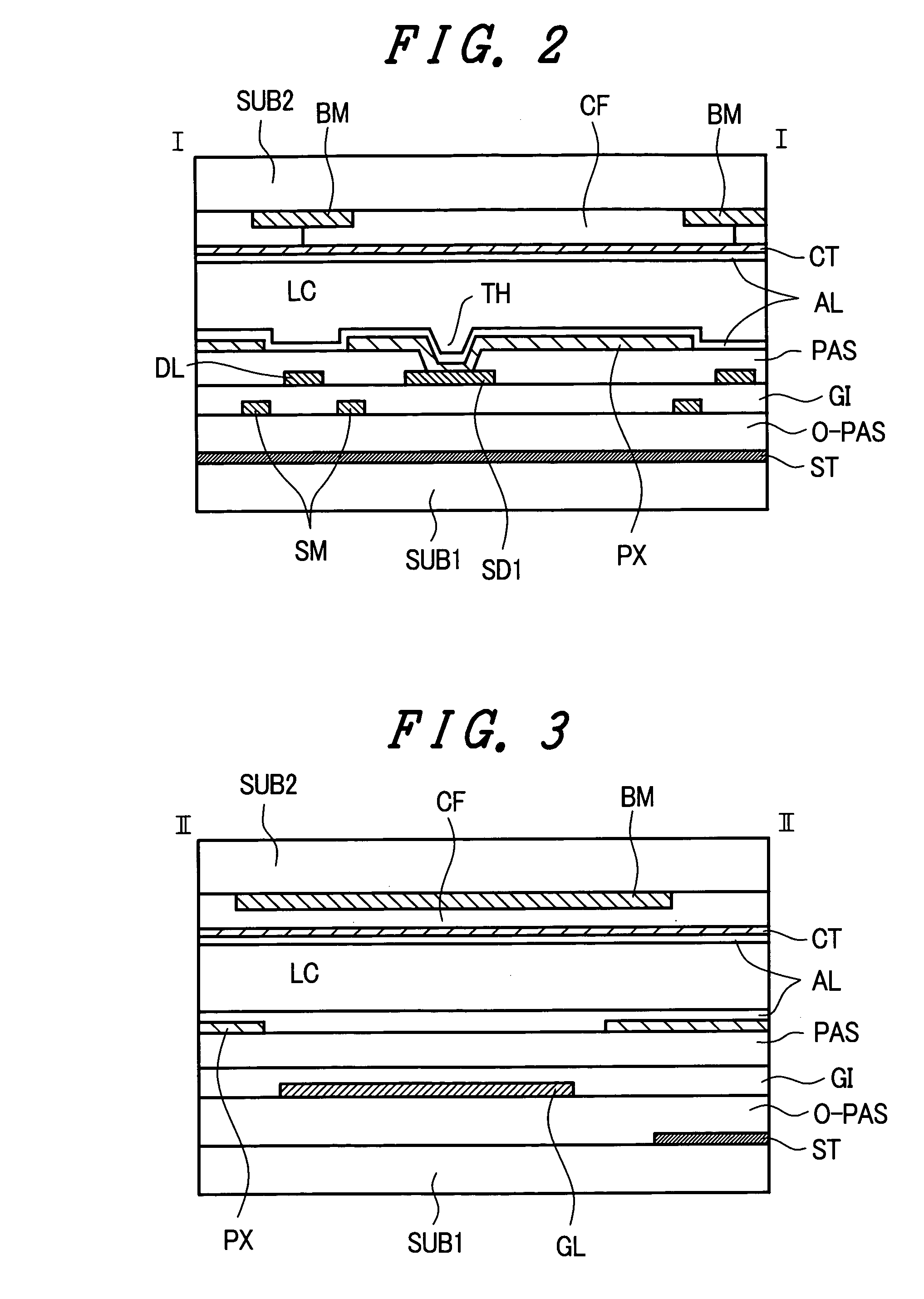
[0306]FIG. 2 is a cross-sectional view taken along a line I-I in FIG. 1 and FIG. 3 is also a cross-sectional view take...

second embodiment

[0317]FIG. 4 is a plan view of the vicinity of one pixel of a vertical field type liquid crystal display device for schematically explaining the pixel constitution of the present invention, FIG. 5 is a cross-sectional view taken along a line I-I in FIG. 4, and FIG. 6 is a cross-sectional view taken along a line II-II in FIG. 4. Reference symbols in the drawings which are equal to those of the previous embodiment indicate identical functioning portions.

[0318] In this embodiment, the reference electrode layer ST has a region which includes regions where the gate line layer GL, the drain line DL and the pixel electrode layer PX of the first substrate SUB1 are formed. The holding capacity is formed between the pixel electrode layer PX and the reference electrode layer ST. According to this embodiment, since the reference electrode layer ST is formed below the gate line layer GL, it is desirable to set the thickness of the organic insulation layer O-PAS to equal to or more than 1 μm, for...

third embodiment

[0320]FIG. 7 is a plan view of the vicinity of one pixel of a vertical field type liquid crystal display device for schematically explaining the pixel constitution of the present invention and FIG. 8 is a cross-sectional view taken along a line I-I in FIG. 7. Reference symbols in the drawings which are equal to those of the previous embodiments indicate identical functioning portions. With respect to the pixel forming layer, over the organic insulation layer O-PAS, the gate line layer GL, the gate insulation layer GI, the drain line layer DL, the thin film transistor TFT, the passivation layer PAS and the pixel electrode PX are formed in this order. The whole or a portion of the pixel electrode PX in the pixel region penetrates the passivation layer PAS and is brought into contact with the gate insulation layer GI.

[0321] Due to such a constitution of this embodiment, in addition to the advantageous effects obtained by respective embodiments, the storage capacity formed between the r...


PUM

PropertyMeasurementUnit
thicknessaaaaaaaaaa
sizeaaaaaaaaaa
organicaaaaaaaaaa

Abstract

Image display device having an electrode forming layer which includes a plurality of gate lines, a plurality of drain lines, a plurality of switching elements and the a plurality of pixel electrodes, and having reference electrode layer between the electrode forming layer and a substrate where the electrode forming layer formed thereon, and the reference electrode layer and the electrode forming layer are insulated by insulating layer.

Description

BACKGROUND OF THE INVENTION [0001] 1. Field of the Invention [0002] The present invention relates to a liquid crystal display device, and more particularly to an active matrix type liquid crystal display device which can reduce holding capacity for holding lighting of pixels for a given time and feeding resistance thereof thus enhancing numerical aperture. [0003] 2. Description of the Related Art [0004] An active matrix type liquid crystal display device generally adopts a system in which liquid crystal is sandwiched between a pair of substrates which face each other in an opposed manner and pixels are selected by pixel electrodes which are driven by a large number of switching elements represented by thin film transistors formed on one of the above-mentioned pair of substrates. One type of the liquid crystal display device adopting such a system is a so-called vertical field type in which on the other substrate (second substrate) which faces one substrate (first substrate) of the a...

Claims


Application Information

Patent Timeline
Patent Type & Authority Applications(United States)
IPC IPC(8): G02F1/1335G02F1/1343G02F1/136G02F1/1362G02F1/1368
CPCG02F1/136213G02F2201/40G02F1/13G02F1/1343G02F1/136286G02F1/136G02F1/133345G02F1/134309G02F1/13439G02F1/1368G02F2201/123
Inventor NAKAYOSHI, YOSHIAKIYANAGAWA, KAZUHIKO
Owner PANASONIC LIQUID CRYSTAL DISPLAY CO LTD
Why Eureka
Try Eureka