
Slider and rotating disk type storage device

a storage device and rotating disk technology, applied in the field of sliders, can solve the problems of deteriorating the reliability of read/write operations of the head, deteriorating the posture of the slider in gimbaled motion, and deteriorating the reliability of the slider's gimbaled motion. achieve the effect of stable kinetic performance and stable kinetic performan

Inactive Publication Date: 2005-12-22
HITACHI GLOBAL STORAGE TECH NETHERLANDS BV
View PDF16 Cites 25 Cited by
  • Summary
  • Abstract
  • Description
  • Claims
  • Application Information

AI Technical Summary

Benefits of technology

[0014] With the recent tendency to an increase in recording density and a decrease in size of magnetic disks, sliders have also been becoming smaller in size. Femto slider defined in IDEMA (International Disk Drive Equipment and Materials Association) is beginning to be used practically. Femto slider is in the shape of a rectangular parallelepiped having external dimensions of 0.7 mm×0.85 mm×0.23 mm, which is smaller than that of the conventional Pico slider (1.0 mm×1.25 mm×0.3 mm). Femto slider is smaller than Pico slider also in the area of an air bearing surface. As the area of an air bearing surface of a slider becomes smaller, the amount of a negative pressure also becomes smaller. Therefore, in order to prevent deterioration in follow-up performance for the surface of a magnetic disk, it is necessary that the amount of a positive pressure and the spring constant of a flexure be set small to keep a flying posture in a well-balanced state.
[0015] In the case of a flexure having a small spring constant, the ability to correct the posture of a slider in gimbaled motions is deteriorated. An air bearing surface of a slider is formed so as to afford such a pressure distribution as enables the most stable kinetic performance to be exhibited in a normal flying posture. Therefore, if the pressure distribution on the air bearing surface in a flying posture is greatly different from that in the normal flying posture, it becomes virtually impossible for the slider to perform proper gimbaled motions, with consequent deterioration in the reliability of read / write operations of the head or the occurrence of an unexpected collision of the slider with the magnetic disk. A solution to this problem may be improving the manufacturing accuracy of HGA and a relative assembling accuracy thereof with respect to the magnetic disk, making the pitch static attitude tolerance and the roll static attitude tolerance more strict to diminish displacement, and diminishing a pressure variation of the air bearing surface in a flying posture relative to the normal flying posture. However, such a solution encounters a limit in both cost and technical aspect. Forming the air bearing surface of the slider in such a manner that the variation in pressure distribution in a flying posture of the slider becomes minimum as compared with that in the normal flying posture is effective in improving the kinetic performance of the slider.

Problems solved by technology

In the case of a flexure having a small spring constant, the ability to correct the posture of a slider in gimbaled motions is deteriorated.
Therefore, if the pressure distribution on the air bearing surface in a flying posture is greatly different from that in the normal flying posture, it becomes virtually impossible for the slider to perform proper gimbaled motions, with consequent deterioration in the reliability of read / write operations of the head or the occurrence of an unexpected collision of the slider with the magnetic disk.
However, such a solution encounters a limit in both cost and technical aspect.

Method used


Image

  • Slider and rotating disk type storage device
  • Slider and rotating disk type storage device
  • Slider and rotating disk type storage device

Examples


Embodiment Construction

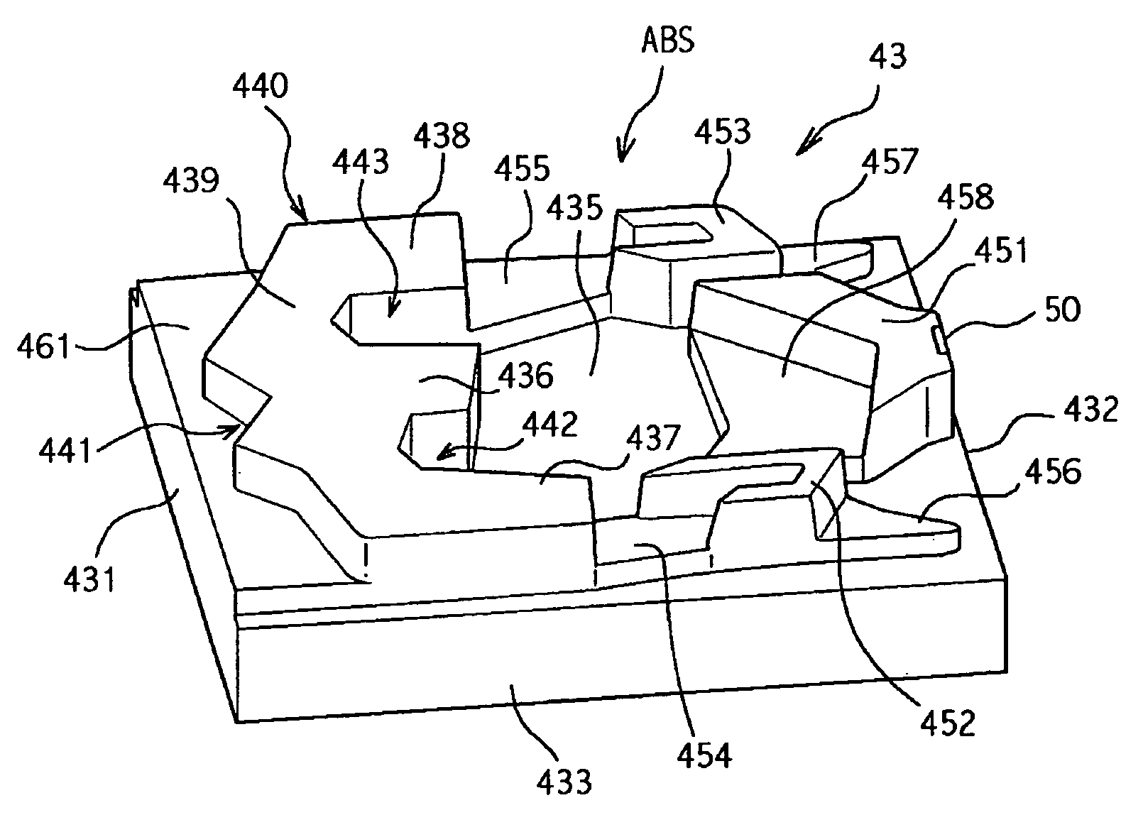
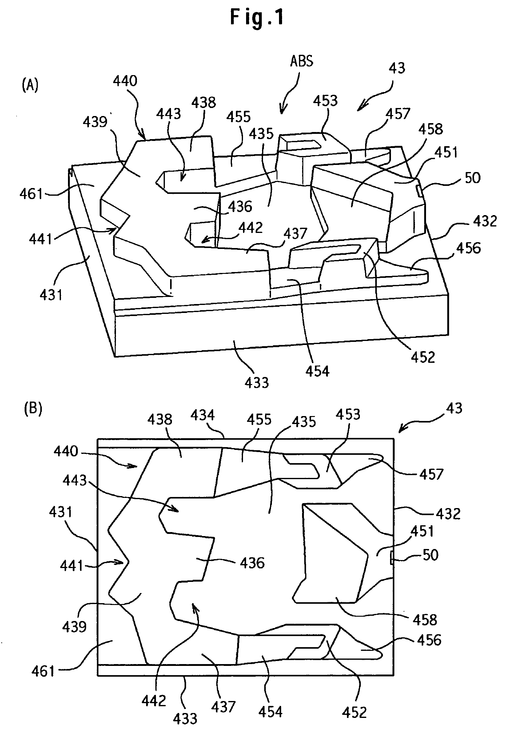
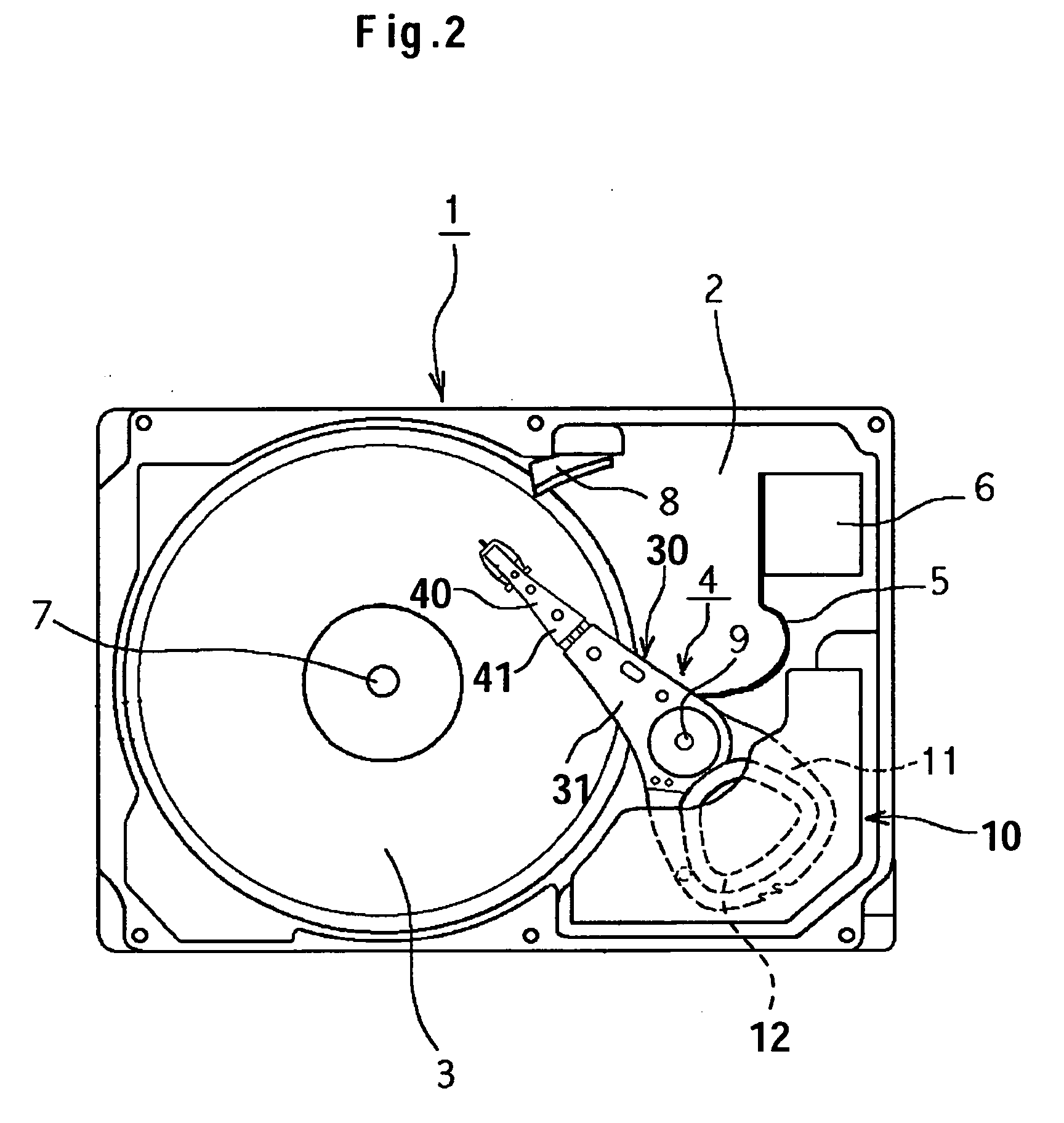
[0040] FIGS. 1(A) and 1(B) show the construction of a slider according to one embodiment of the present invention, in which FIG. 1(A) is a perspective view and FIG. 1(B) is a plan view. FIG. 2 is a plan view showing a schematic construction of a magnetic disk drive according to the present invention. FIG. 3 is a plan view of a flexure as seen from a magnetic disk side. FIG. 4 is a side view showing a schematic structure of a side face of the flexure illustrated in FIG. 3.

[0041] A magnetic disk drive as an example of a rotating disk type storage device according to the present embodiment includes as follows. As shown in FIG. 2, a magnetic disk 3 as a rotating disk type storage medium, a spindle motor (not shown), and an actuator head suspension assembly (hereinafter referred to as “AHSA”) 4 are accommodated within a disk enclosure 1. The enclosure 1 has a hermetically sealed space formed by a base 2 and a cover (not shown) covering the base 2 from above. A flexible cable 5 and an ex...


PUM

PropertyMeasurementUnit
radiusaaaaaaaaaa
lengthaaaaaaaaaa
lengthaaaaaaaaaa

Abstract

A stable kinetic performance is to be exhibited even in the case of such a small-sized slider as Femto slider. In one embodiment, an air bearing surface (ABS) of a slider comprises a first pad constituting portion extending from a leading edge side to a trailing edge side, a second pad constituting portion and a third pad constituting portion formed on both sides of the first pad constituting portion and extending from the leading edge side to the trailing edge side, a connecting pad for connecting the first, second, and third pad constituting portions on the leading edge side, a first negative pressure portion formed by the first and second pad constituting portions and the connecting pad, a second negative pressure portion formed by the first and third pad constituting portions and the connecting pad, and an air trap portion formed on the leading edge side of the connecting pad.

Description

CROSS-REFERENCES TO RELATED APPLICATIONS [0001] This application claims priority from Japanese Patent Application No. JP2004-180957, filed Jun. 18, 2004, the full disclosure of which is incorporated herein by reference. BACKGROUND OF THE INVENTION [0002] The present invention relates to a slider for use in a rotating disk type storage device and more particularly to a slider able to exhibit a stable kinetic performance. [0003] In a rotating disk type storage device such as a magnetic disk drive or a magnetic optical disk drive, a slider with a head mounted thereon moves while flying over a surface of a rotating disk. A magnetic disk drive will now be described as an example. The slider is supported by a spring structure called a flexure. The flexure is attached to a support structure called a load beam. An assembly comprising the slider, the flexure, and the load beam is designated a head gimbals assembly (hereinafter referred to as “HGA”). The HGA is attached to an actuator perform...

Claims


Application Information

Patent Timeline
Patent Type & Authority Applications(United States)
IPC IPC(8): G11B5/60
CPCG11B5/6005G11B5/6082
Inventor INOUE, HIROONAKAMURA, TAICHIOKASAKA, KAZUTAKASERA, AKIHIRO
Owner HITACHI GLOBAL STORAGE TECH NETHERLANDS BV
Learn More