Culture microscope and computer program controlling culture microscope

Inactive Publication Date: 2005-12-22
OLYMPUS CORP
View PDF8 Cites 78 Cited by
  • Summary
  • Abstract
  • Description
  • Claims
  • Application Information

AI Technical Summary

Benefits of technology

[0012] A culture microscope according to this invention has an incubator chamber in which a culture environment for cells is controlled, an imaging de

Problems solved by technology

Organisms have high complexity.
It is therefore not e

Method used


Image

  • Culture microscope and computer program controlling culture microscope
  • Culture microscope and computer program controlling culture microscope
  • Culture microscope and computer program controlling culture microscope

Examples


first embodiment

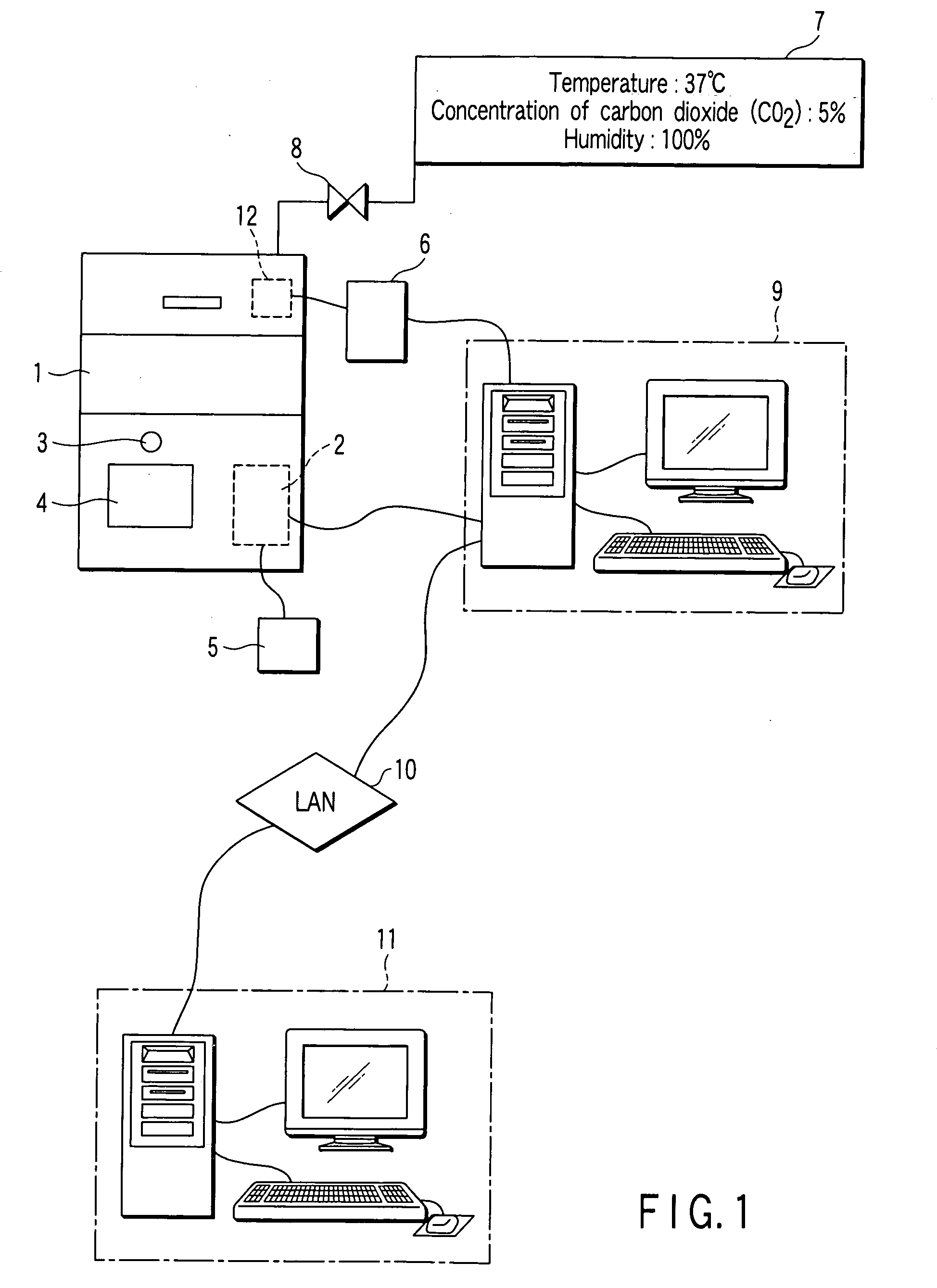
[0031] A first embodiment according to the invention will be described, with reference to the accompanying drawings. FIG. 1 is a conceptual representation of an apparatus according to the present invention.

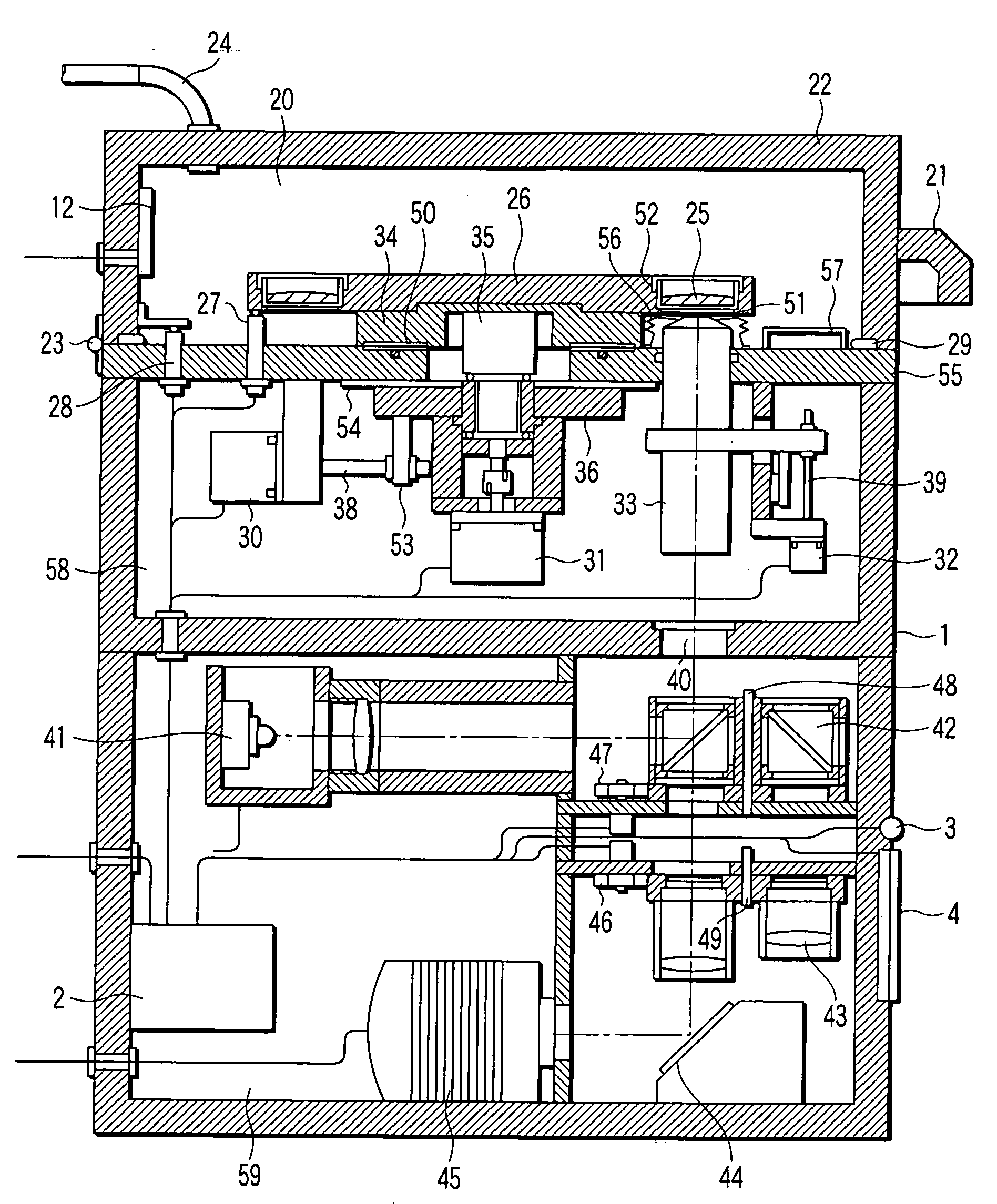
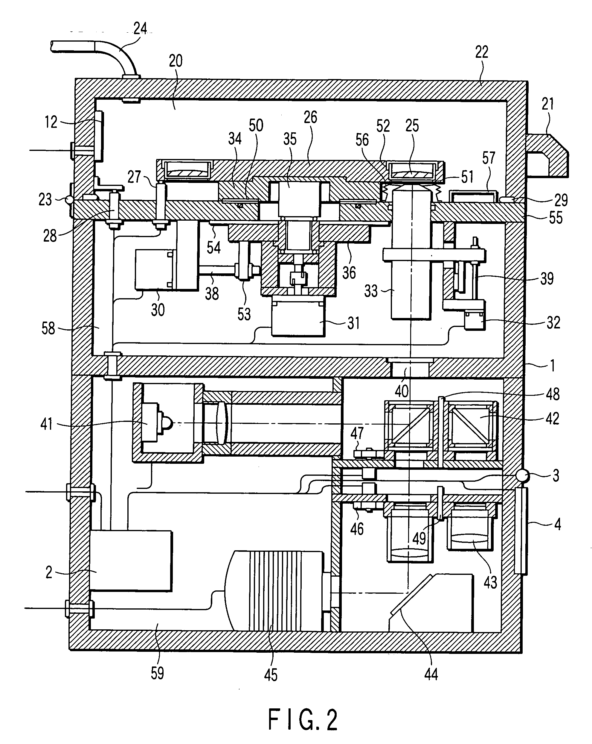
[0032] A culture microscope main body 1 contains an incubator chamber, in which cells are cultured. The chamber is integrated with a microscope section that is used to observe a cell. The main body 1 contains a controller 2. The controller 2 controls other component, described later. The controller 2 is arranged in the main body 1, thus reducing the space occupied by the culture microscope. Nonetheless, the controller 2 may be arranged outside the main body 1 if the heat that it generates while operating may influence other components provided in the main body 1. The culture microscope main body 1 further has an alarm buzzer 3 and an alarm display 4. The alarm buzzer 3 generates an alarm when any trouble occurs during the experiment or the operation. The alarm display 4 displays a...

second embodiment

[0080] the present invention will be described with reference to the accompanying drawings.

[0081] The apparatus configuration, the program for preparing observation and the program for starting observation are the same as those in the first embodiment. Therefore, they will not be described in detail.

[0082]FIG. 15 depicts the alarm buzzer 3 and the alarm display 4. The alarm display 4 can display the information as displayed in the monitor of the computer 9 and / or as in the form of characters and the like. The display 4 can display, for example, the dialog 85 shown in FIG. 10 for prompting the operator to replace the culture medium that has been explained in conjunction with step S17 in FIG. 6B. The dialog 85 helps the operator to determine whether the culture medium is readily replaced or not, because the replacing of the culture medium is often carried out in the vicinity of the culture microscope main body 1.

[0083] Moreover, the alarm buzzer 3 may be driven to generate an alarm ...


PUM


Abstract

A culture microscope has an incubator chamber which controls a culture environment in which cells are cultured, an imaging optical system which photographs the cells, and a controller which controls a time-lapse photographing performed by the imaging optical system.

Description

CROSS-REFERENCE TO RELATED APPLICATIONS [0001] This application is based upon and claims the benefit of priority from the prior Japanese Patent Application No. 2004-155897, filed May 26, 2004, the entire contents of which are incorporated herein by reference. BACKGROUND OF THE INVENTION [0002] 1. Field of the Invention [0003] The present invention relates to a microscope combined with a culture apparatus. More particularly, the invention relates to a culture microscope which is used to observe and photograph a sample of a living biological system, e.g., a living cell, for a long time. [0004] 2. Description of the Related Art [0005] Organisms have high complexity. It is therefore not easy to understand their configurations or functions. In view of this, a simple experimental system is employed, which uses a cultured cell as a minimum unit that can represent life events. Use of a cultured cell can accomplish an experiment in which an analysis of, e.g., responses of hormones, is not af...

Claims


Application Information

Patent Timeline
IPC IPC(8): C12M1/00C12M1/34
CPCC12M23/50C12M41/14C12M41/36G02B21/367G02B21/0088G02B21/24G02B21/362C12M41/46
Inventor KAGAYAMA, AKITSUGU
Owner OLYMPUS CORP
Why Eureka
Try Eureka