Discretionarily adjustable friction block and tackle balance system and uses thereof

a technology of friction block and adjustable friction, which is applied in the direction of wing opener, multi-purpose tools, constructions, etc., can solve the problems of increasing the force exerted by the tension device, improperly balanced window sash placement, and inability to adjust the friction force, etc., to achieve the effect of improving the discretionarily adjustable friction block, easily and effectively

Inactive Publication Date: 2005-12-29
WU MINGZE
View PDF16 Cites 15 Cited by
  • Summary
  • Abstract
  • Description
  • Claims
  • Application Information

AI Technical Summary

Benefits of technology

[0006] It is an object of this invention to provide an improved discretionarily adjustable friction block and tackle balance which can support a wide range of window sash sizes and weights. The adjustable friction block and tackle balance of this invention is based on both U-shaped and square-shaped tube. The desired amount of friction can be adjusted simply, easily and effectively after installation of the adjustable friction block and tackle balance in a window.

Problems solved by technology

A drawback of the window balance system of U.S. Pat. No. 3,358,404 is that the friction force cannot be adjusted.
As the window is closed from the partially open position, the tension device is caused to stretch, further increasing the amount of force exerted by the tension device.
However an improperly balanced window sash will not stay wherever it is set, i.e., it will “hop” if overbalanced or “drop” if under-balanced.
Making or storing different models of window sash balance system to account for the different weights and sizes of windows or window sashes adds to the overall cost of window balance systems.
However, in U.S. Pat. No. 4,517,766, adjustment of the friction force cannot be easily performed after the block and tackle balance system has been installed in a window because the operating or access space is too narrow to turn the adjust screw.
In U.S. Pat. No. 4,697,304, a rivet is used to adjust the friction drag against balance cord, but the rivet cannot be easily inserted into or taken out of the tube after the balance is installed in a window.
Therefore, adjusting the friction drag against the cord is not available.
None of the prior block and tackle balance systems have overcome the fundamental issues or problems of using preferably one friction-adjustable block and tackle balance system for balancing window sashes and the like of widely varying sizes and weights.

Method used


Image

  • Discretionarily adjustable friction block and tackle balance system and uses thereof
  • Discretionarily adjustable friction block and tackle balance system and uses thereof
  • Discretionarily adjustable friction block and tackle balance system and uses thereof

Examples


example 1

Adjustable Balance System having a U-shaped tube and Corresponding Components

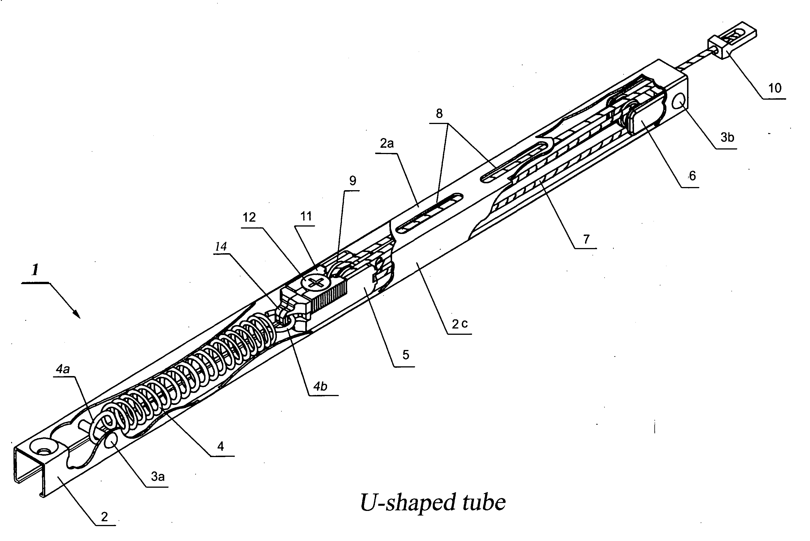
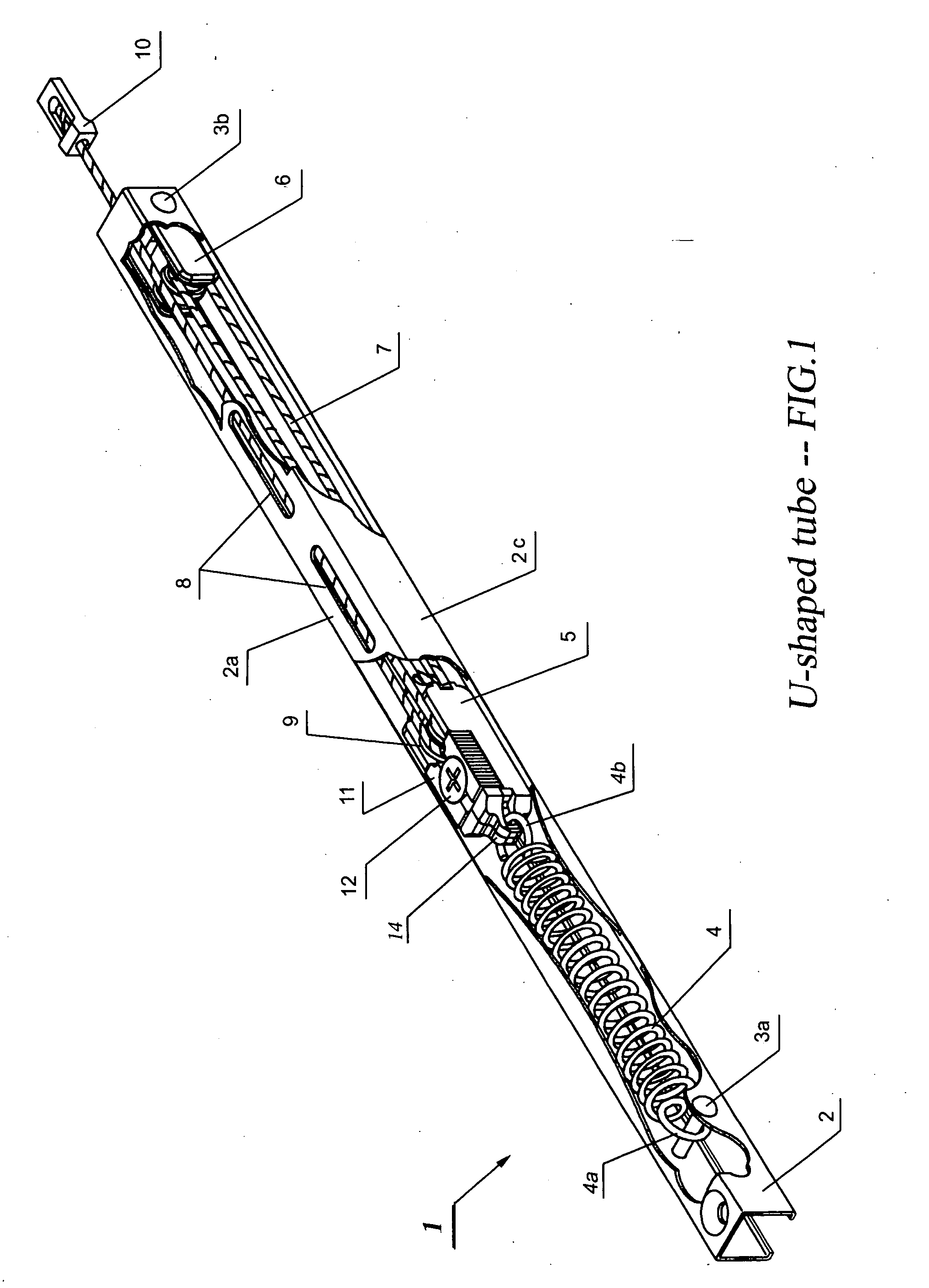
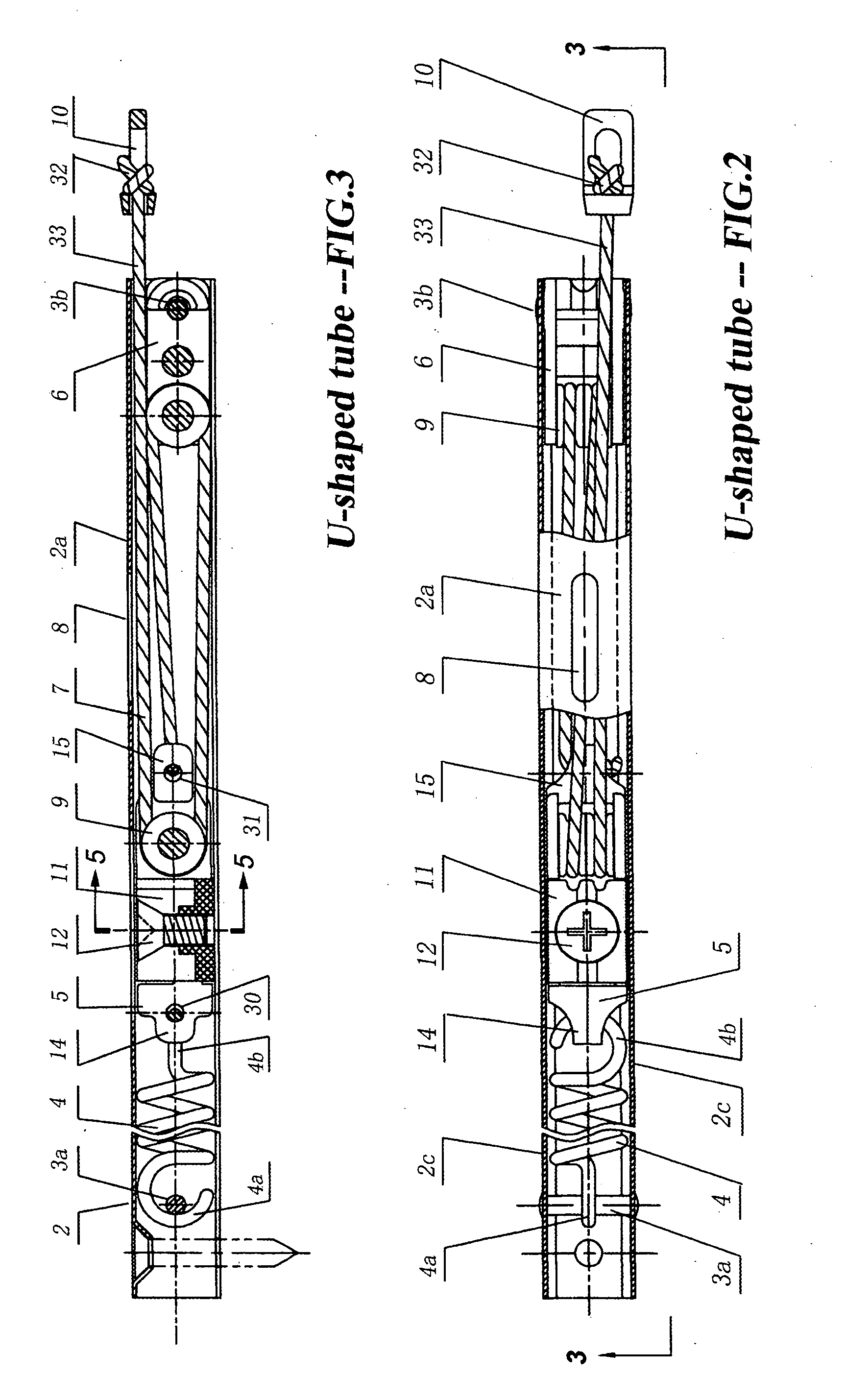
[0039] For a general understanding of an adjustable balance system 1 of the present invention having a U-shaped tube, reference is made to the drawings FIG. 1 to FIG. 6.

[0040] An adjustable balance system 1 of this invention as shown in FIG. 1 comprising a U-shaped elongated tube 2, a coil spring 4, a floating anchor subassembly 5, a fixed anchor subassembly 6, a cord 7 and a hook 10.

[0041] The U-shaped tube 2 has one topside 2a and two sidewalls 2c, shown in FIG. 1 and FIG. 2. There is on the topside 2a at least one hole or slit referred to herein as adjust hole 8 for exposing and for adjusting the adjust screw 12. The adjust screw 12 is rotatably mounted on the adjustable break 11 for splaying or contracting the adjustable break 11. The adjustable break increases or decreases the friction force between the inner surface of the tube and the floating anchor subassembly 5. In an embodiment, the floating a...

example 2

Adjustable Balance System having a square-shaped tube or rectangular-shaped tube and Corresponding Components

[0056] In an embodiment of the adjustable friction force block and tackle window balance system 101 of this invention, the tube 102 is square-shaped or rectangular-shaped. An adjustable friction force block and tackle window balance system as shown in FIG. 7 comprises an elongated tube 102 having four sides, a coil spring 4, a floating anchor subassembly 105, a fixed anchor subassembly 6, a cord 7 and a hook 10.

[0057] In an embodiment, all the components of the adjustable balance system as shown in FIG. 7 are similar to the parts of the adjustable balance system as shown in FIG. 1, except for the floating anchor subassembly 105 and the square-shaped or rectangular-shaped tube 102. The floating anchor subassembly 105 as shown in FIG. 7 is specially designed for the square-shaped or rectangular-shaped tube 102. The square-shaped or rectangular-shaped tube 102 will be collecti...


PUM


Abstract

Disclosed is a discretionarily adjustable friction force block and tackle balance system comprising a housing and an adjustable break, wherein means are provided for adjusting the friction force between an inner surface of the housing and the adjustable break. An adjustable balance system comprising a housing, a floating anchor assembly, a fixed anchor assembly, a cord, and an elastic suspension is also disclosed. In an embodiment, the housing is a 3-side or 4-side tube or channel. There is at least one elongated hole or slit on at least one surface of said housing. An adjustable break is mounted inside the floating anchor subassembly. Moving the window sash also causes the floating anchor subassembly to move. When the floating anchor subassembly is moved to a position just under elongated hole on the said housing, the adjust screw installed in the adjustable break is exposed. The desired friction force can be easily created and adjusted by turning the adjust screw in the appropriate direction to splay or retract the adjustable break for balancing window sashes having widely varying sizes and weights.

Description

[0001] This application claims the benefit of U.S. Ser. No. 60 / 582,443, filed Jun. 24, 2004. The contents of this application are hereby incorporated in their entireties by reference into this application. [0002] Throughout this application, various publications are referenced. Disclosures of these publications in their entireties are hereby incorporated by reference into this application to more fully describe the state of the art to which this invention pertains.BACKGROUND OF THE INVENTION [0003] Block and tackle window balance system is a type of window balance device which has been known and in use for more than 30 years. U.S. Pat. No. 3,358,404 disclosed a typical construction of the block and tackle window balance system. A drawback of the window balance system of U.S. Pat. No. 3,358,404 is that the friction force cannot be adjusted. Ideally, the window balance assembly will be constructed such that the forces exerted on the window sash from the tension device and gravity will...

Claims


Application Information

Patent Timeline
Patent Type & Authority Applications(United States)
IPC IPC(8): E05C17/64E05D15/22E05F1/00
CPCE05D13/08E05D13/1207E05D15/22Y10T16/64E05Y2900/148Y10T16/63E05Y2201/67
Inventor WU, MINGZE
Owner WU MINGZE
Why Eureka
Try Eureka