Latch assembly

a technology of latching mechanism and assembly, which is applied in the direction of keyhole guards, mechanical control devices, instruments, etc., can solve the problems of increasing the complexity and cost of the manufacturing process, and the inability to close the latching mechanism, so as to facilitate the operation, reduce the complexity and cost, and reduce the cost

Inactive Publication Date: 2005-12-29
HARDWARE IMPORTS
View PDF10 Cites 10 Cited by
  • Summary
  • Abstract
  • Description
  • Claims
  • Application Information

AI Technical Summary

Benefits of technology

[0004] It is an object of the present invention to provide a latch device which is simple to manufacture and which has few parts.
[0005] It is a further object of the present invention to provide a latch closure mechanism which may be closed when the latch locking mechanism is in a locked position, to facilitate ease of operation and to prevent potential damage to the latch.
[0006] It is a further object of the present invention to provide a latch closure with two releasable closure positions—a first partially closed position and a second fully closed position—both of which securely retain a closure striker and may not be forced to the open position.

Problems solved by technology

These problems and drawbacks include the use of many parts and often complicated combinations of motions between the parts to provide open, closed and locked positions, thereby tending to increase the complexity and cost of the manufacturing process.
Additionally, it is often not possible to close the latching mechanism when it is in the locked position.

Method used


Image

  • Latch assembly
  • Latch assembly
  • Latch assembly

Examples


Embodiment Construction

Preferred Embodiments of the Latch Assembly Rotary Mechanism

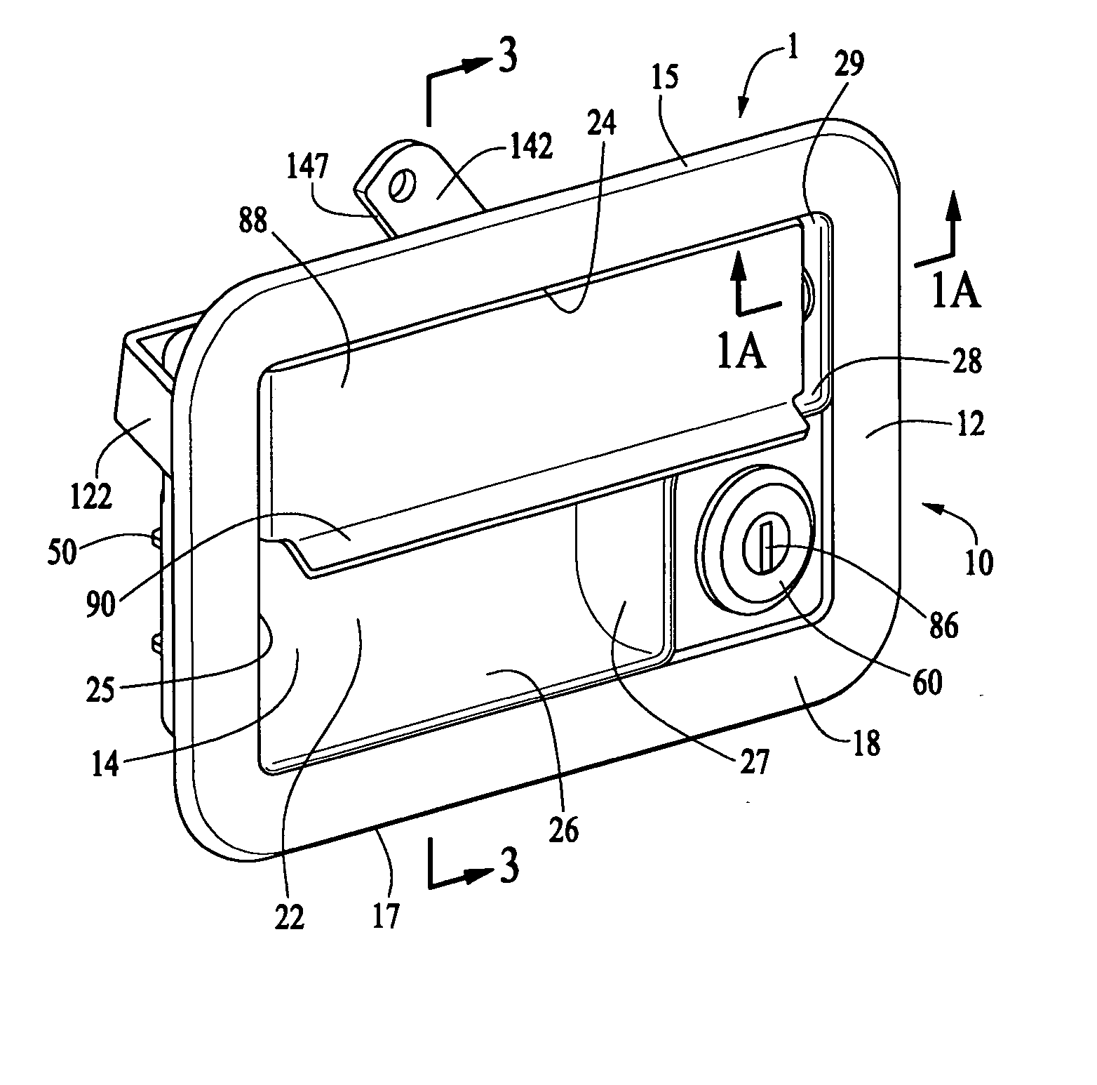
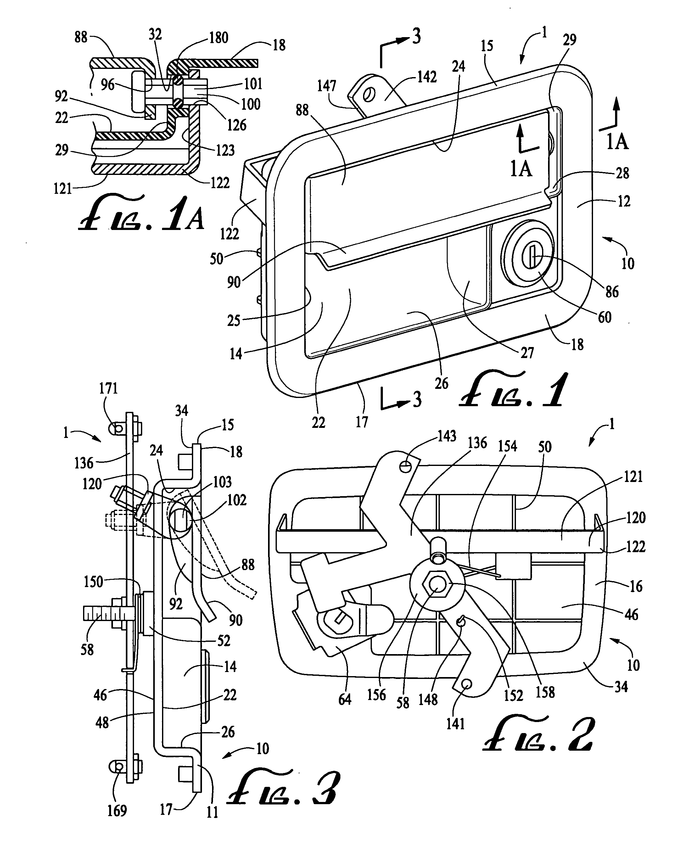
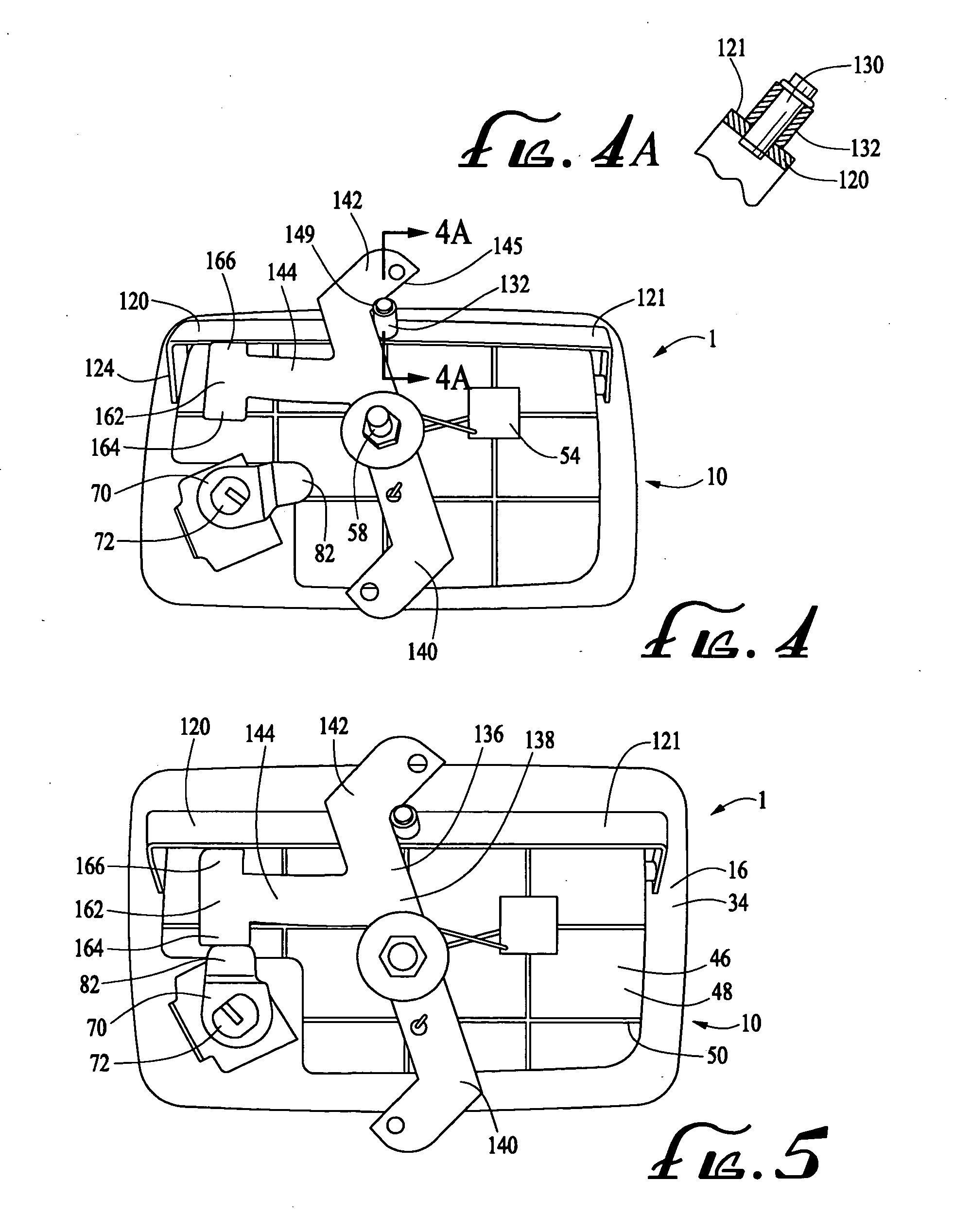
[0038] With reference to FIGS. 1, 1A, 2, 3, 4, 4A and 5, a latch assembly rotary mechanism (1) including a housing (10) formed of an essentially rigid impact resistant and corrosion resistant material such as a polymer or metal, and having a housing wall (11) which may vary in thickness from on the order of about 2 mm to on the order of about 8 mm. It is preferred that the housing be made of high impact polymeric material, metal or other material having the necessary rigidity and strength. The housing (10) includes a front side (12), in which a cavity (14) is formed, and a back side (16), as well as a top edge (15) and a bottom edge (17). Front side (12) includes substantially flat front surface (18) and lock mechanism mounting opening (20) (not shown) which penetrates the housing (10). Also, included in front side (12) of housing (10) is cavity floor (22) and cavity walls (24), (25), (26), (27), (28) and (29) joining wit...


PUM


Abstract

The present invention provides a latch assembly of the type commonly used on commercial vehicles which is simple to manufacture and has few parts. The latch assembly secures a closure element, or striker, in either of two secure positions by means of independently operable dual linear latch bolts and may be closed when the locking mechanism is in a locked position, to facilitate ease of operation and to prevent damage to the latch. The latch bolts are releasable by operation of a remotely located handle actuated rotary latch mechanism.

Description

FIELD OF INVENTION [0001] The present invention is directed to a latch assembly of the type commonly used on commercial vehicles, including tradesmen's specialized truck bodies, recreational vehicles, tool boxes, storage lockers and sheds, out buildings and the like. The present invention provides a latch assembly for retaining a striker element securely in either of two positions releasable by operation of a handle actuated rotary mechanism. [0002] Conventional locks and latch assemblies of the kind commonly used in the above described applications have exhibited a number of problems and drawbacks which the present invention is intended to resolve or improve upon. These problems and drawbacks include the use of many parts and often complicated combinations of motions between the parts to provide open, closed and locked positions, thereby tending to increase the complexity and cost of the manufacturing process. Additionally, it is often not possible to close the latching mechanism w...

Claims


Application Information

Patent Timeline
Patent Type & Authority Applications(United States)
IPC IPC(8): E05B13/00E05B63/14E05C1/14E05C9/04
CPCE05B13/004E05C9/043E05C1/145E05B63/14Y10T70/5761
Inventor GULLEY, THOMAS DEANGLOVER, FRANK E.
Owner HARDWARE IMPORTS
Why Eureka
Try Eureka