Piezoelectric vibrating segment, supporting structure for piezoelectric vibrating segment, piezoelectric vibrator, and piezoelectric vibrating gyroscope

a piezoelectric vibrating and supporting structure technology, applied in the direction of turn-sensitive devices, instruments, devices, etc., can solve the problems of easy suppression of difficult to keep stable excited vibration and stable sensing vibration, etc., to achieve simplified and miniaturized structure, more stable support, and increased fixing strength

Inactive Publication Date: 2005-12-29
SEIKO EPSON CORP
View PDF11 Cites 48 Cited by
  • Summary
  • Abstract
  • Description
  • Claims
  • Application Information

AI Technical Summary

Benefits of technology

[0009] An aspect of the invention is to provide a piezoelectric vibrating segment, a supporting structure for a piezoelectric vibrating segment, a piezoelectric vibrator, and a piezoelectric vibrating gyroscope capable of keeping a stable excited vibration and a stable sensing vibration even against vibrations or impacts from the outside. Further, an object of the invention is to provide a piezoelectric vibrating segment, a supporting structure for a piezoelectric vibrating segment, a piezoelectric vibrator, and a piezoelectric vibrating gyroscope in which the excited vibration and the sensing vibration are hard to be suppressed if the piezoelectric vibrating segment is supported.
[0043] According to the invention, since the piezoelectric vibrating segment comprises the elastic beams, the piezoelectric vibrating segment can be provided in which the excited vibrations and the sensing vibration are kept stable, and the excited vibrations and the sensing vibrations are hard to be affected by supporting the piezoelectric vibrating segment if vibrations or impacts are applied from the outside.

Problems solved by technology

As a result, a problem arises that the piezoelectric vibrating segment abuts on the supporting stage to make it difficult to keep the stable excited vibration and the stable sensing vibration.
Moreover, another problem arises that the excited vibration and the sensing vibration are easy to be suppressed by supporting the piezoelectric vibrating segment.

Method used


Image

  • Piezoelectric vibrating segment, supporting structure for piezoelectric vibrating segment, piezoelectric vibrator, and piezoelectric vibrating gyroscope
  • Piezoelectric vibrating segment, supporting structure for piezoelectric vibrating segment, piezoelectric vibrator, and piezoelectric vibrating gyroscope
  • Piezoelectric vibrating segment, supporting structure for piezoelectric vibrating segment, piezoelectric vibrator, and piezoelectric vibrating gyroscope

Examples


embodiment 1

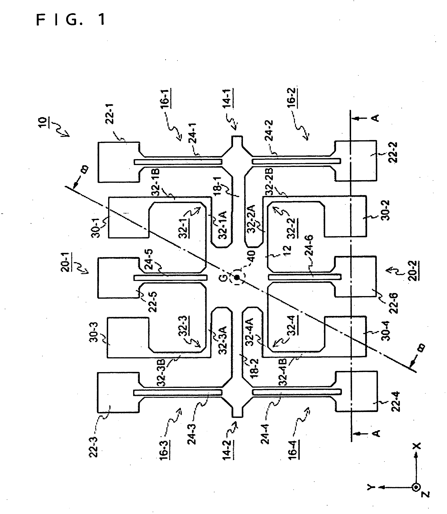
[0090] Hereinafter, the electrode pattern of the piezoelectric vibrating segment 10 according to the exemplary embodiment is described referring to FIGS. 2 and 3. FIG. 2 is a plan view showing an electrode pattern in one principal surface of the piezoelectric vibrating segment according to the present And, FIG. 3 is a plan view showing an electrode pattern in the other principal surface thereof. Here, the principal surface denotes a surface of the piezoelectric vibrating segment 10 parallel to the X-Y plane, the surface shown in FIG. 3 facing the substrate 60 as a supporting stage in a supporting structure for the piezoelectric vibrating segment 10 as described below (See FIG. 12.). In these drawings the elements shown in FIG. 1 are denoted with the same reference numerals, and descriptions therefor are omitted here. In FIGS. 2 and 3, checked portions denote conduction electrodes, and for ease of discriminating plural types of electrodes they are denoted with hatching, vertical str...

exemplary embodiment 1

[0104] As described above, in the supporting structure for the piezoelectric vibrating segment 10 of the exemplary embodiment 1, the conductive adhesive 70 is used as the fixing member for supporting and fixing the five points including the four of the first supporting sections 30-1, 30-2, 30-3, and 30-4 and the second supporting section 40 provided on the piezoelectric vibrating segment 10. Further, the structure also providing electrical connection with the vibrating segment mounting electrode lands 61-1, 61-2, 61-3, 61-4, and 61-5 formed on the substrate 60.

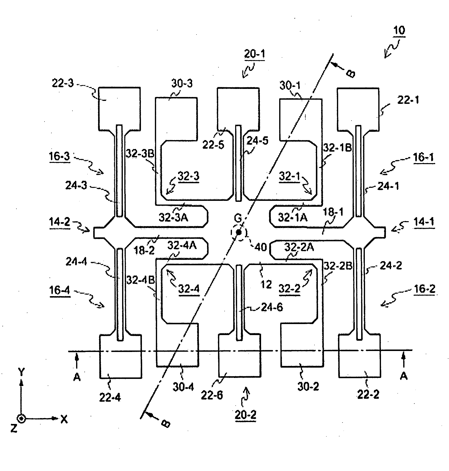
[0105] Hereinafter, an operation of the piezoelectric vibrating segment 10 supported by the supporting structure according to the present embodiment 1. the piezoelectric vibrating segment 10 absorbs vibrations generated in the periphery of the base section 12 by distortion of the beams 32-1, 32-2, 32-3, and 32-4. Thus, if portions (specifically the first supporting sections 30-1, 30-2, 30-3, and 30-4) other than the center por...

embodiment 2

[0133] Hereinafter, an operation of the piezoelectric vibrating segment 110 according to the exemplary embodiment is described. FIGS. 16 and 17 are plan views schematically showing vibration forms of the detection vibration in the piezoelectric vibrating segment 110 according to the present As is the case with FIGS. 10 and 11, each of the vibration arms and beams is illustrated with a line and each of the supporting sections is illustrated with a dot. The vibration form corresponding to the solid lines in FIG. 9 is shown in FIG. 16, and the vibration form corresponding to the broken lines in FIG. 9 is shown in FIG. 17. The same elements as those in FIGS. 13 and 14 are denoted with the same reference numeral, and descriptions thereof are omitted.


PUM


Abstract

Aspects of the invention can provide piezoelectric vibrating segment, a supporting structure for the piezoelectric vibrating segment, piezoelectric vibrator, and the piezoelectric vibrating gyroscope capable of maintaining stable excited vibrations and stable sensing vibrations. The piezoelectric vibrating segment can include a base section, a plurality of excited vibration arms and sensing vibration arms radially extending from the base section in a single plane. A plurality of first beams having elasticity extending from the base section and between the vibration arms and, at least, a first supporting section formed on the tips of the beams can be formed. The excited vibration arms and the sensing vibration arms are provided with electrode patterns formed thereon to be connected to and driven by a semiconductor device. The piezoelectric segment is encapsulated by a container composed of a base member and a lid member to form a piezoelectric vibrator and a piezoelectric vibrating gyroscope, and stable excited vibrations and stable sensing vibrations are maintained.

Description

BACKGROUND OF THE INVENTION [0001] 1. Field of Invention [0002] The invention relates to a piezoelectric vibrating segment, a supporting structure for a piezoelectric vibrating segment, a piezoelectric vibrator, and a piezoelectric vibrating gyroscope. [0003] 2. Description of Related Art [0004] Piezoelectric vibrating gyroscopes that use piezoelectric vibrating segments or piezoelectric vibrators having the piezoelectric vibrating segments housed in containers have been used as angular velocity sensors for detecting rotational angular velocities in rotational systems. The piezoelectric vibrating gyroscopes are used for car navigation systems or for detecting camera vibration of VTRs or still cameras. [0005] For the piezoelectric vibrating gyroscopes, there are used piezoelectric vibrating segments composed of vibrating arms extending in a single plane and base sections for connecting the vibrating arms. The piezoelectric vibrating gyroscopes drive the piezoelectric vibrating segmen...

Claims


Application Information

Patent Timeline
Patent Type & Authority Applications(United States)
IPC IPC(8): G01C19/56G01C19/5628H01L41/08H01L41/09H01L41/18H01L41/22H01L41/311H03H9/09H03H9/17
CPCG01C19/5719G01C19/56
Inventor KARAKI, EIJIKAWAUCHI, OSAMU
Owner SEIKO EPSON CORP
Why Eureka
Try Eureka