
Method for hydrate plug removal

Active Publication Date: 2005-12-29
DEN NORSKE STATS OLJESELSKAP AS +1
View PDF12 Cites 39 Cited by
  • Summary
  • Abstract
  • Description
  • Claims
  • Application Information

AI Technical Summary

Benefits of technology

[0013] The return flow line may include any pipe or sections of pipes, such as steel pipe, flexible pipe, composite pipe, reinforced pipe or polymer pipe. However, said return flow line is preferably coiled tubing in particular preferred embodiument coiled tubing retained on one single spool and retrievable by a spool drive as fully inserted into the pipeline with the pig disconnected. The term coiled tubing in this context emphasises any metal pipe, composite pipe, polymer pipe, reinforced pipe or flexible pipe that can be wound onto a spool of a size feasible for handling. The return flow line is preferably dimensioned to be retrieved as fully inserted in the pipe only when the pig is disconnected, resulting in significant savings in labor, weight and cost.
[0015] Preferably a blanking plug is set in the pig as the return flow line is disconnected, to blank the bore left after disconnecting the return flow line, to increase the thrusting area.
[0020] In another preferred embodiment of the invention, the thruster pig is inserted into the pipeline from a subsea pig launching chamber in connection with the pipeline, with a thrusting fluid line and a coiled tubing line arranged from said launching chamber to a surface vessel containing coiled tubing, thrusting fluid and means for equipment and fluid handling. For said embodiment the thrusting fluid line can be a coiled tubing line and the insertion of the thrusting pig into the launching chamber can be facilitated by using remotely controlled vehicles. Said embodiment may reduce the requirements as to equipment, for example by avoiding a steel riser from the launching chamber to the surface vessel.

Problems solved by technology

Hence, hydrate plug removal preferably takes place when the thruster pig encounters an obstruction in form of hydrates hindering the advancement of the pig, resulting in increased differential pressure over the pig and thereby opening of the apertures and nozzles for hydrate plug removal by spraying coolant.

Method used


Image

  • Method for hydrate plug removal
  • Method for hydrate plug removal
  • Method for hydrate plug removal

Examples


Embodiment Construction

[0024] Preferred embodiments of the invention and its advantages are best understood by reference to FIGS. 1 and 2 wherein like numbers refer to like and corresponding parts.

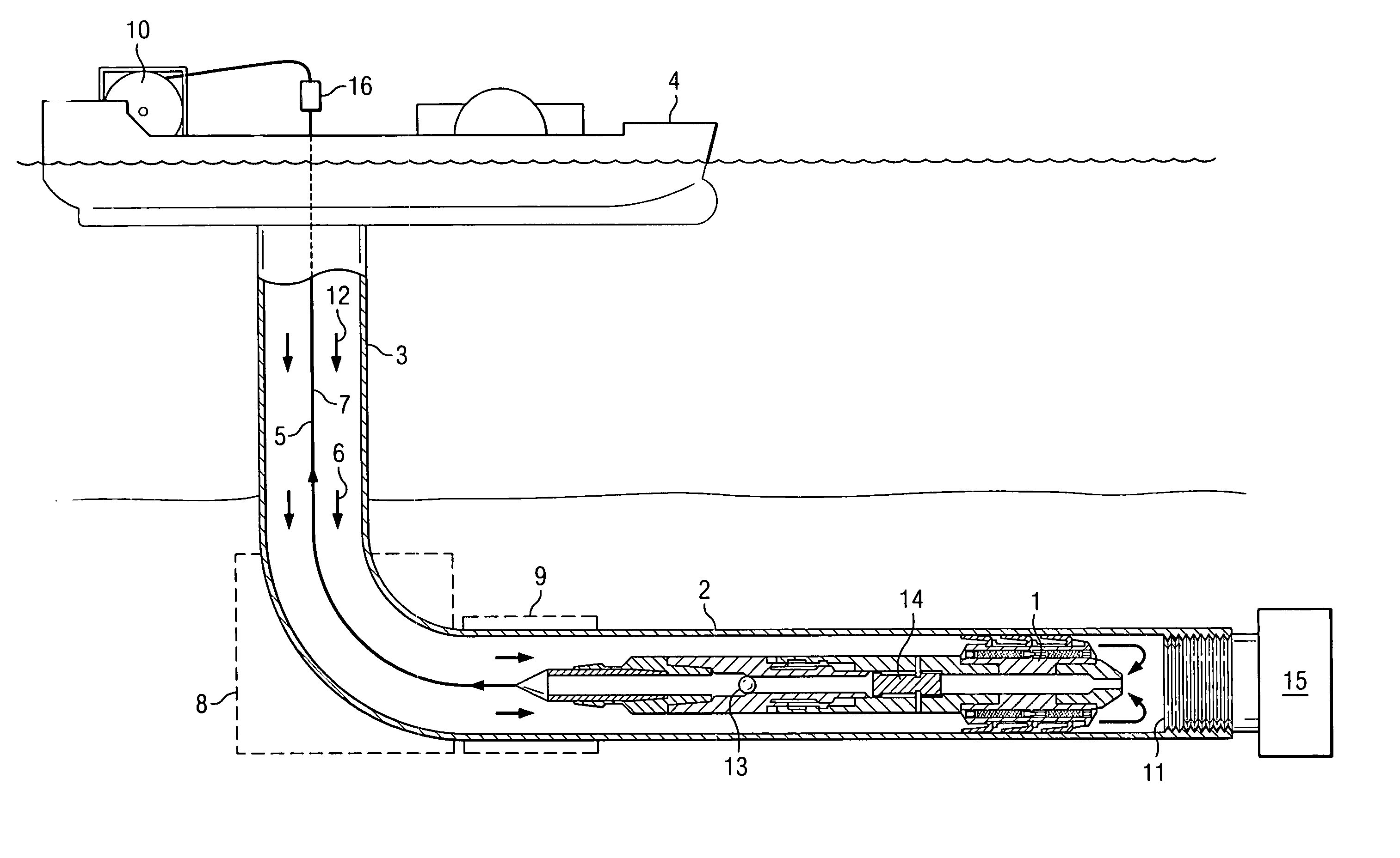
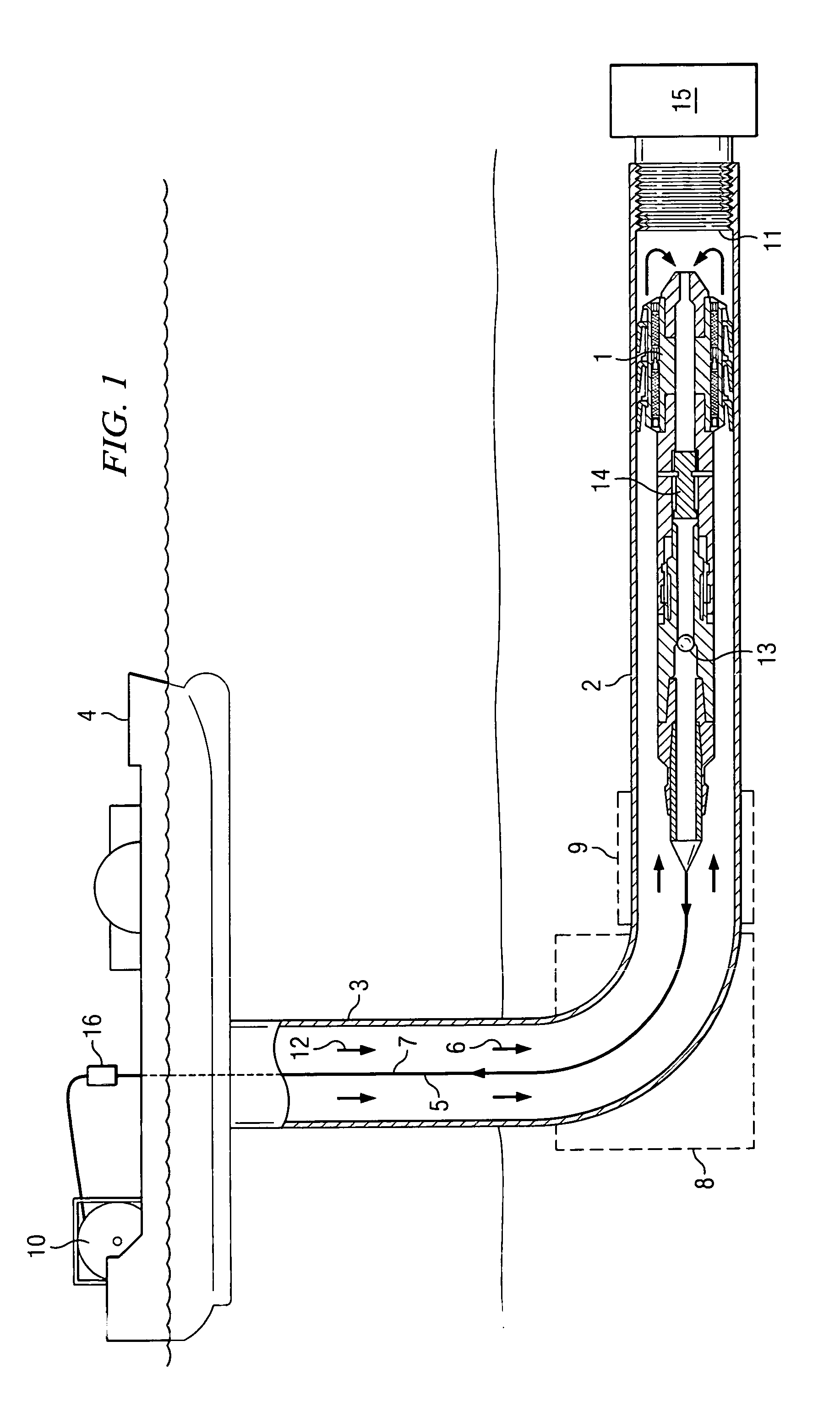
[0025] Reference is now made to FIG. 1, which is a schematic illustration of the overall system used with the method for removal of deposits from a pipeline according to the present invention, in the illustrated embodiment for removal of hydrate plugs. A thruster pig 1 is illustrated as located in a pipeline 2. Pipeline 2 is connected via a riser section 3 to a surface vessel 4. Thruster pig 1 is urged into pipeline 2 via riser 3 by pumping a thrusting fluid from vessel 4. The thrusting fluid urges thruster pig 1 forward into pipeline 2, and a coiled tubing return flow line 5 is connected to thruster pig 1 and pulled into the pipeline 2 as the thruster pig 1 is urged forward by the thrusting fluid. Coiled tubing return fluid line 5 conducts return fluid from ahead of thruster pig 1. The fluid flow is provided b...


PUM


Abstract

A method for removal of deposits such as hydrate plugs from a pipeline is provided including inserting a thruster pig connected to a return flow line into the pipeline The pig is then advanced forward into the pipeline by pumping a thrusting fluid into an annulus between the pipeline and the return flow line while removing deposits continuously or intermittently and returning flow as appropriate from ahead of the pig through the return flow line. The return flow line is then disconnected from the pig after sufficient deposit removal and retrieved from the return flow line. Next, the pig may then be transported through the pipeline by the pipeline fluid to a pig receiving location once the pipeline flow is resumed.

Description

RELATED APPLICATIONS [0001] The present invention claims the benefit of Norwegian patent application ______ entitled, “Method for Hydrate Plug Removal” filed on Jun. 24, 2004. [0002] The present invention is related to copending patent application Ser. No. ______ entitled, “Thruster Pig” which claims the benefit of Norwegian Patent Application No. ______ filed on Jun. 24, 2004.FIELD OF THE INVENTION [0003] The present invention relates to methods for removal of hydrates, ice, wax and other deposits from pipes. More particularly, the present invention relates to a method for removal of deposits from pipelines using a specific thruster pig, particularly in long subsea pipelines. BACKGROUND OF THE INVENTION [0004] Hydrates are clathrate compounds, i.e. inclusion complexes, formed by the reaction of molecules of water and another substance such as a hydrocarbon, in which the molecule of water H—OH bond is not split. Particularly in the oil and gas industry the demand for hydrate removal...

Claims


Application Information

Patent Timeline
IPC IPC(8): B08B9/00F16LF16L55/38
CPCF16L2101/12F16L55/38
Inventor KINNARI, KEIJOLABES-CARRIER, CATHERINECRAWFORD, JIM BOBKIRSPEL, LARRY J.TORRANCE, BILL
Owner DEN NORSKE STATS OLJESELSKAP AS
Features
  • Generate Ideas
  • Intellectual Property
  • Life Sciences
  • Materials
  • Tech Scout
  • Unparalleled Data Quality
  • Higher Quality Content
  • 60% Fewer Hallucinations
Learn More