
Method of preventing reuse in an analyte measuring system

a technology of analyte measuring system and reuse method, which is applied in the field of test strips, can solve the problems of infecting a second user, causing problems, and accidentally testing a previously used test strip by users, and achieves the effect of increasing resistan

Inactive Publication Date: 2005-12-29
LIFESCAN INC
View PDF58 Cites 16 Cited by
  • Summary
  • Abstract
  • Description
  • Claims
  • Application Information

AI Technical Summary

Benefits of technology

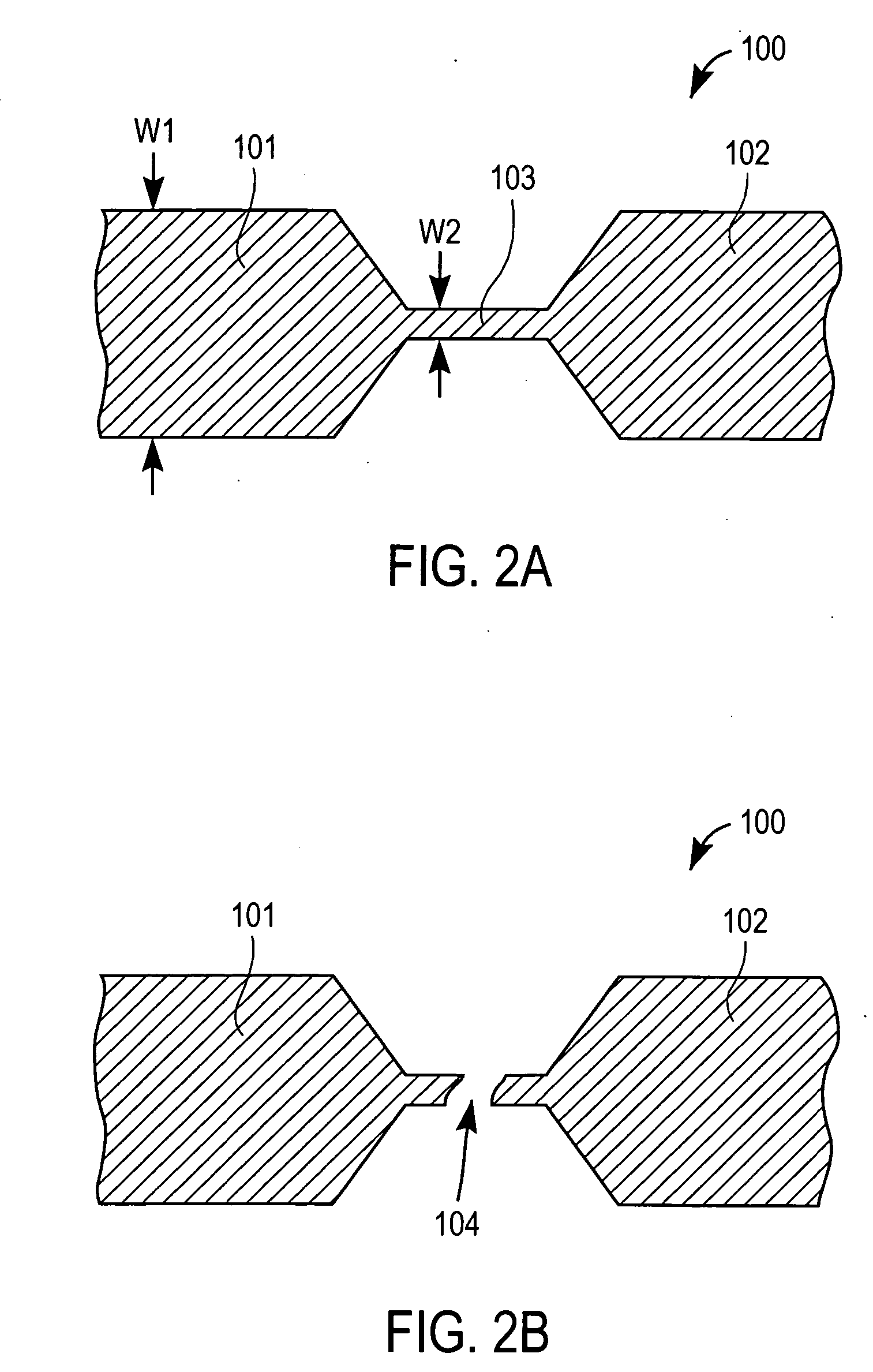
[0006] The present invention is directed to a method of preventing the reuse of a test strip in an analyte measuring system wherein the method includes the steps of inserting a test trip into a meter; detecting an electrical continuity with said meter between a first electrical contact zone and a second electrical contact zone; applying a physiological sample to the disposable test trip; measuring a signal from the test strip that corresponds to an analyte concentration; and applying a voltage between said first and second electrical contact zone sufficient to destroy a frangible link between said first electrical contact and said second electrical contact.
[0007] In a further embodiment of the present invention, a method of preventing the reuse of the test strips further includes the steps of: providing a fuse zone between said first and second electrical contact zones, wherein said fuse zone has a higher resistance than the first and second electrical contact zones.
[0008] In a further embodiment of a method according to the present invention, the analyte measuring system wherein the conductive trace has a positive temperature coefficient of resistance, the conductive trace being a material chosen from a group consisting of carbon, silver, platinum, palladium, gold, Ir, Pt, tungsten, copper, and aluminum. In a further embodiment of the present invention, the fuse zone melts, forming an open circuit, when the predetermined voltage is applied between said first electrical contact and said second electrical contact wherever the predetermined voltage may range from about 1.5 volts to about 30 volts.
[0009] In further embodiments of the method of the present invention, the analyte measuring system may also include one or more of the following elements, an integrated lance; a working electrode and a reference electrode; a reagent layer is disposed on at least a portion of said working electrode wherein said reagent layer may be a redox mediator and a redox enzyme; and a silica filler.

Problems solved by technology

This requirement is often needed because the reagent chemistry in many test strips is not suitable for measuring glucose a second time.
However, it is possible that some user will accidentally test a previously used test strip.
This could potentially become a problem if the glucose meter attempts to make a glucose measurement and outputs a result.
For the case in which test strips are integrated with a lancing device, there is an added potential problem in that the re-use of test strips may result in cross-contamination.
The lancing portion of the integrated device may have blood remaining on it which could infect a second user who might accidentally use the test strip.

Method used


Image

  • Method of preventing reuse in an analyte measuring system
  • Method of preventing reuse in an analyte measuring system
  • Method of preventing reuse in an analyte measuring system

Examples


Embodiment Construction

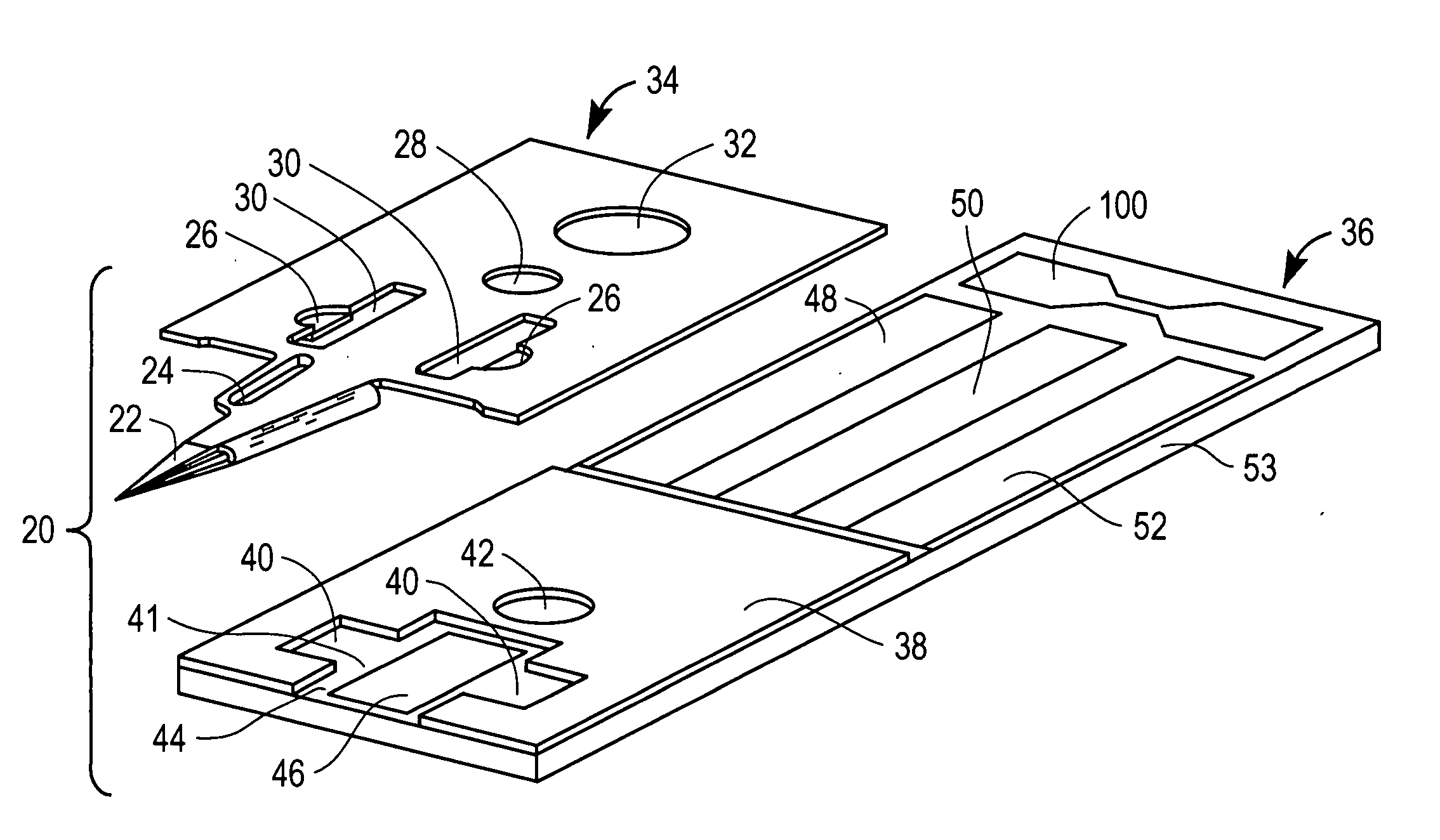
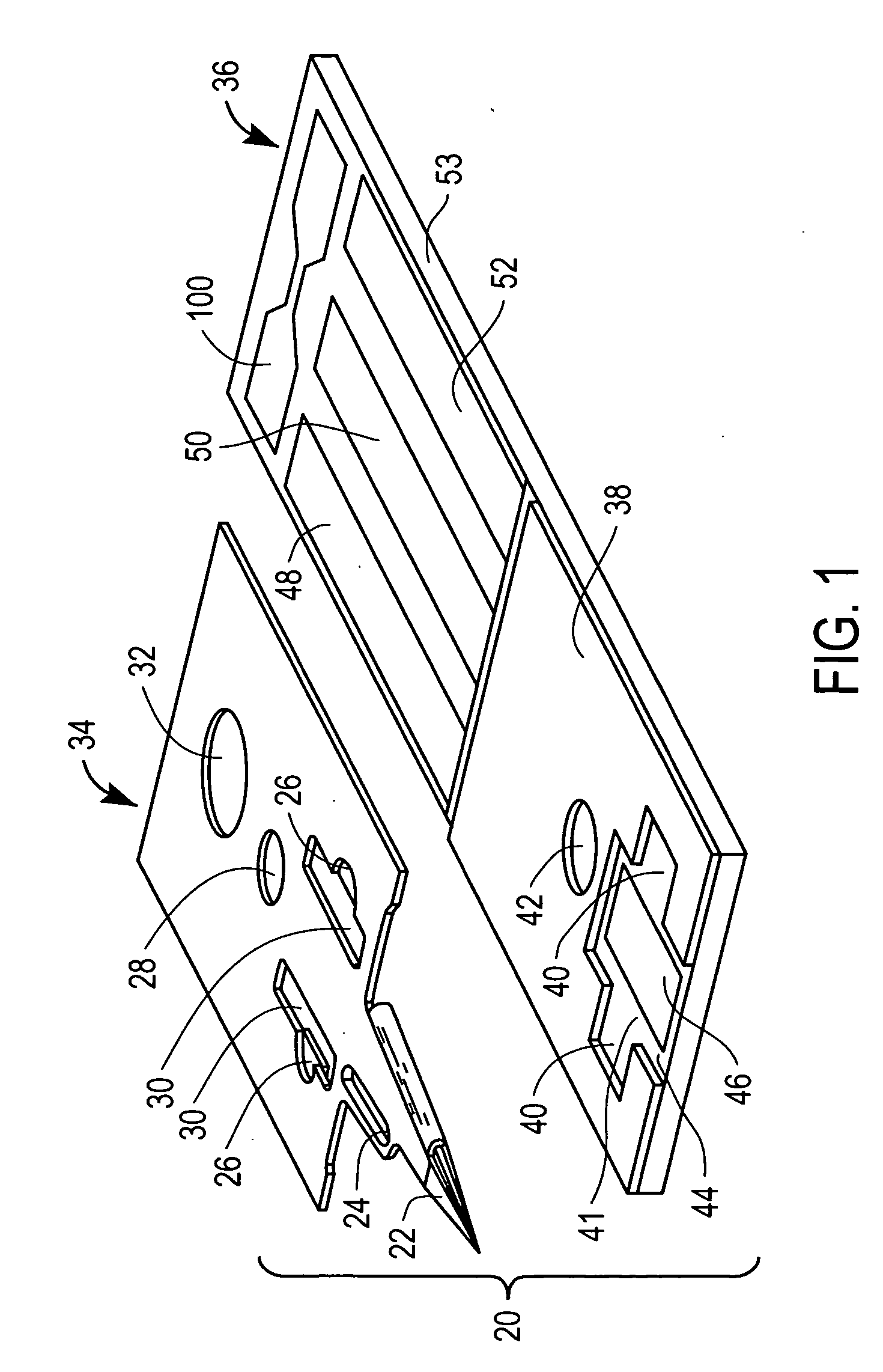
[0018]FIG. 1 is a top perspective view of a test strip 20 according to the present invention. In this embodiment test strip 20 includes a first portion, in this case a top layer 34; a fixing mechanism, in this case an adhesive layer 38; and a second portion, in this case a bottom layer 36. In this example embodiment, bottom layer 36 includes a conductive layer which is deposed on a substrate 53. The conductive layer includes a first working electrode 48, a second working electrode 50, a reference electrode 52, and a frangible mechanism such as a fuse 100 here in the form of a frangible conductive pad. First working electrode 48, second working electrode 50, and reference electrode 52 may be in the form of a conductive pad. Top layer 34 includes the roof of sample receiving chamber 41. In an embodiment of the present invention, top layer 34 further includes an integrated lance 22, a stiffening rib 24, side embossment spacers 26, vents 30, a distal embossment spacer 28, and a registra...


PUM

PropertyMeasurementUnit
voltagesaaaaaaaaaa
voltageaaaaaaaaaa
voltageaaaaaaaaaa

Abstract

The present invention is a method of preventing reuse of test strips for measuring an analyte or indicator such as glucose in a physiological fluid such as blood, interstitial fluid, or urine. The present invention also relates to a method of preventing reuse of test strips incorporating an integrated lance such as a needle, blade, or other sharp or skin puncturing device. Certain types of medical devices such as, for example, glucose test strips were intended to be tested only once and then disposed. This requirement is often needed because the reagent chemistry in many test strips is not suitable for measuring glucose a second time. However, it is possible that some user will accidentally test a previously used test strip. This could potentially become a problem if the glucose meter attempts to make a glucose measurement and outputs a result. Therefore, it is desirable that a single use test strip and meter have a prescribed method for preventing a previously tested test strip from being reused.

Description

CROSS-REFERENCE [0001] This application is related to co-pending provisional application Ser. No. 60 / 422,228, filed on Oct. 30, 2002, entitled “Improved Method of Lancing Skin for the Extraction of Blood” (attorney docket number LFS-0264) which is hereby incorporated herein by reference. This application is also related to co-pending international application serial number PCT / GB01 / 05634, filed on Dec. 19, 2001, entitled “Analyte Measurement” which are hereby incorporated herein by reference. This application is also related to co-pending provisional application Ser. No. 60 / 458,242, filed on Mar. 28, 2003, entitled “Integrated Lance and Strip for Analyte Measurement” (attorney docket number LFS-5011) which are hereby incorporated herein by reference. This application is related to co-pending provisional application Ser. No. 60 / 459,465, filed on Mar. 28, 2003, entitled “Method of Analyte Measurement Using Integrated Lance and Strip” (attorney docket number LFS-5012) which are hereby ...

Claims


Application Information

Patent Timeline
Patent Type & Authority Applications(United States)
IPC IPC(8): A61BA61B5/15B01L3/00B01L99/00G01N21/78G01N27/26G01N33/487G01N33/52G01N37/00H01H37/76
CPCA61B5/1411A61B2560/0276A61B2562/0295B01L3/5027B01L3/502707G01N33/48771B01L2200/141B01L2300/0645B01L2300/0825B01L2400/0406B01L3/502715A61B5/150022A61B5/150213A61B5/150358A61B5/150442A61B5/150923A61B5/15186G01N33/49G01N33/50G01N33/48
Inventor ALLEN, JOHN J.
Owner LIFESCAN INC
Learn More