Heat-generating component cooling structure

a cooling structure and heat generation technology, applied in the construction details of electrical appliances, basic electric elements, lighting and heating apparatuses, etc., can solve the problems of degrading insulation of semiconductor modules, generating a large amount of heat, and affecting the cooling effect of components

Active Publication Date: 2005-12-29
SANSHA ELECTRIC MFG
View PDF17 Cites 54 Cited by
  • Summary
  • Abstract
  • Description
  • Claims
  • Application Information

AI Technical Summary

Benefits of technology

[0005] A cooling structure for a heat-generating component according to the present invention includes a hollow heat sink having a portion made of a thermally conductive material. The hollow heat sink has an interior path formed therein which extends from first to second ends of the heat sink. A fan is disposed to face the first end of the heat sink, being in contact with or spaced therefrom. A heat-generating component of an electrical circuit is mounted on a portion other than the interior path in the heat sink, e.g. on an outer surface of the heat sink. It is desirable to form fins on the walls of the interior path of the heat sink. Also, it is desirable to form a layer of an oxide of stain-preventing metal, e.g. titanium, on the walls of the interior path.

Problems solved by technology

Some of such electric components generate a large amount of heat when supplied with current thereto.
The connection terminals of the semiconductor modules of this power supply apparatus are adversely affected by undesirable components, if any, in external air sucked into the interior of the power supply apparatus, and, therefore, insulation of the semiconductor modules would be degraded.
However, when such power supply apparatus is used in electroplating, it will be in an environment in which a mist of liquid generated from a plating bath tank is flowing, and, therefore, even with a large insulation distance held, air containing the plating liquid mist should contact the connection terminals of the semiconductor modules, whereby the insulation is degraded. this could lead to failure of the modules.
Such conductive particles would be sucked into the interior of the power supply apparatus, accumulate over the connection terminals of the semiconductor modules, and cause current leakage, which could lead to failure of the semiconductor modules.

Method used


Image

  • Heat-generating component cooling structure
  • Heat-generating component cooling structure
  • Heat-generating component cooling structure

Examples


Embodiment Construction

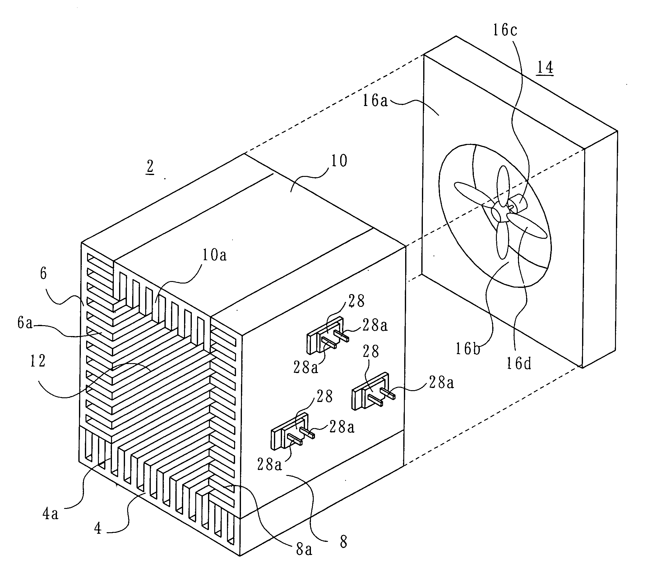
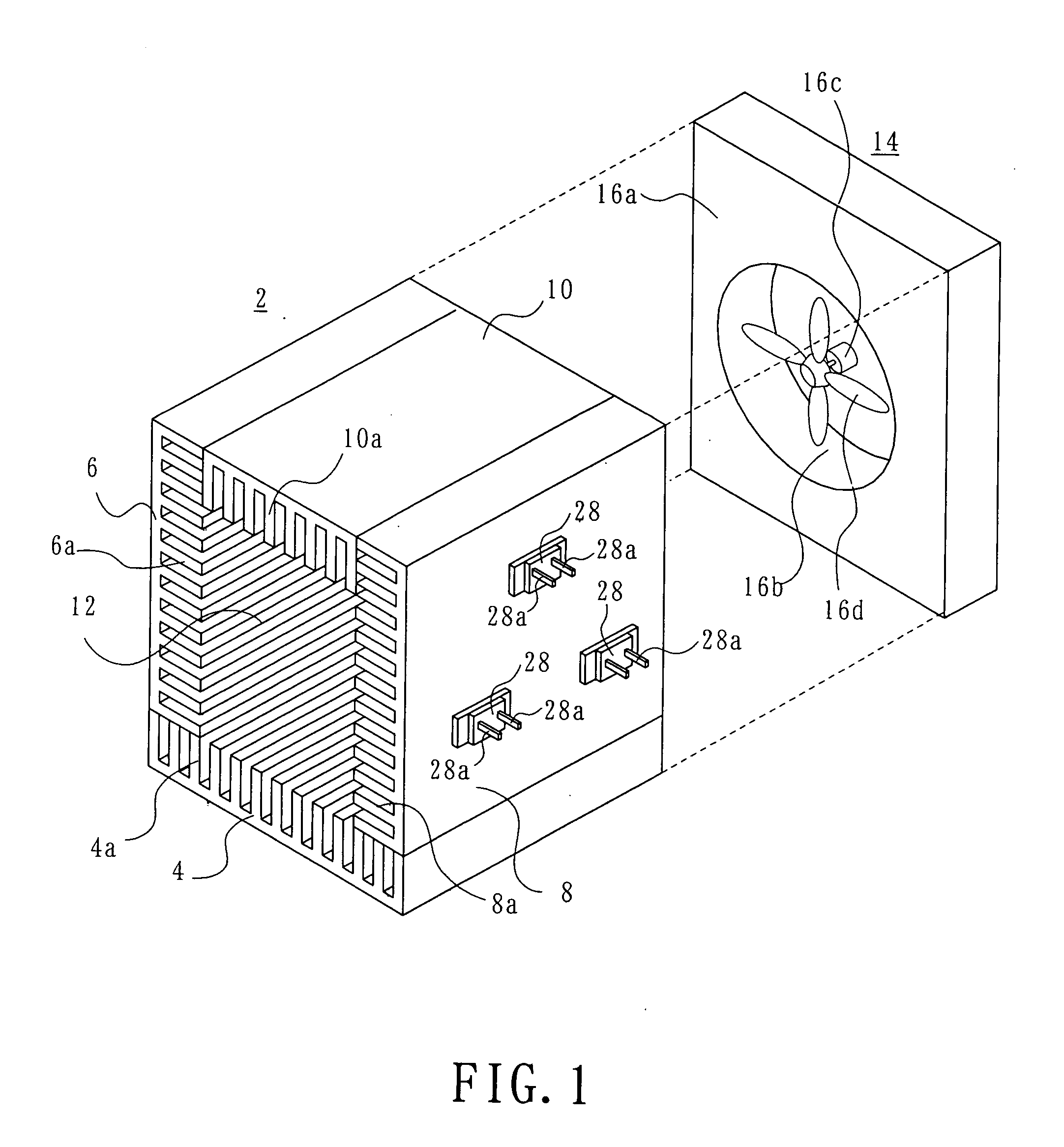
[0013] As shown in FIG. 1, a heat-generating component cooling structure according to a first embodiment includes a hollow heat sink 2. The heat sink 2 includes a plurality of heat conductive material members combined to form a heat sink having a polygonal cross-section. For example, four metal plate members 4, 6, 8 and 10 are disposed perpendicular to each other into a rectangular-parallelepiped-shaped heat sink 2, with adjacent plate members secured to each other by means of any suitable securing members (not shown). The heat sink 2 has a path 12 formed in it, which extends between and opening at two opposed ends, e.g. front and rear end portions. The plate members 4, 6, 8 and 10 have a number of fins 4a, 6a, 8a and 10a, respectively, formed on their surfaces facing the path 12. The respective fins extend in the length direction of the path 12. The metal plate members 4, 6, 8 and 10 may be formed by, for example, drawing aluminum.

[0014] In the rear portion of the heat sink 2, a f...


PUM


Abstract

A heat-generating component cooling structure includes a hollow heat sink having a portion made of a thermally conductive material. The heat sink has an interior path extending from first to second ends of the heat sink. A fan device is disposed at the first end of the heat sink and is adapted to cause air to flow through the interior path. Fins are disposed in the path in the heat sink. Heat-generating components of an electrical circuit are mounted on an outer surface of the heat sink.

Description

[0001] This invention relates to a cooling structure for a heat-generating component. BACKGROUND OF THE INVENTION [0002] A power supply apparatus, an electronic load device (active dummy load) and the like include a number of electric components. Some of such electric components generate a large amount of heat when supplied with current thereto. Hereinafter, such components are referred to as heat-generating components. It is desirable for heat-generating components to be cooled. An example of useable cooling techniques is a forced air cooling method. An example of power supply apparatuses employing a forced air cooling technique is disclosed in JP 2003-244958 A. The power supply apparatus disclosed in JP 2003-244958 A includes a rectangular-parallelepiped-shaped heat sink having two side surfaces to which first and second plate-shaped chassis are attached. Each of the chassis has a window therein. A semiconductor module, which is a heat-generating component, is mounted on the heat ...

Claims


Application Information

Patent Timeline
Patent Type & Authority Applications(United States)
IPC IPC(8): H01L23/467H02M3/28H05K7/20
CPCH01L23/467H05K7/20918H01L2924/0002H01L2924/00
Inventor ISHII, HIDEOKATOOKA, MASAONAKATA, KAZUNORIIKEJIRI, YUJI
Owner SANSHA ELECTRIC MFG
Why Eureka
Try Eureka