
Small profile hanger system for ceiling suspended lighting fixtures

a hanging system and ceiling technology, applied in the field of hanging system of ceiling suspended lighting fixtures, can solve the problems of not contributing to an aesthetically pleasing hanging system and relatively large diameter of the self, and achieve the effects of reducing the size of the hole, increasing the strength of the stem and cross bar, and increasing the material of the stem

Inactive Publication Date: 2005-12-29
ABL IP HLDG
View PDF10 Cites 14 Cited by
  • Summary
  • Abstract
  • Description
  • Claims
  • Application Information

AI Technical Summary

Benefits of technology

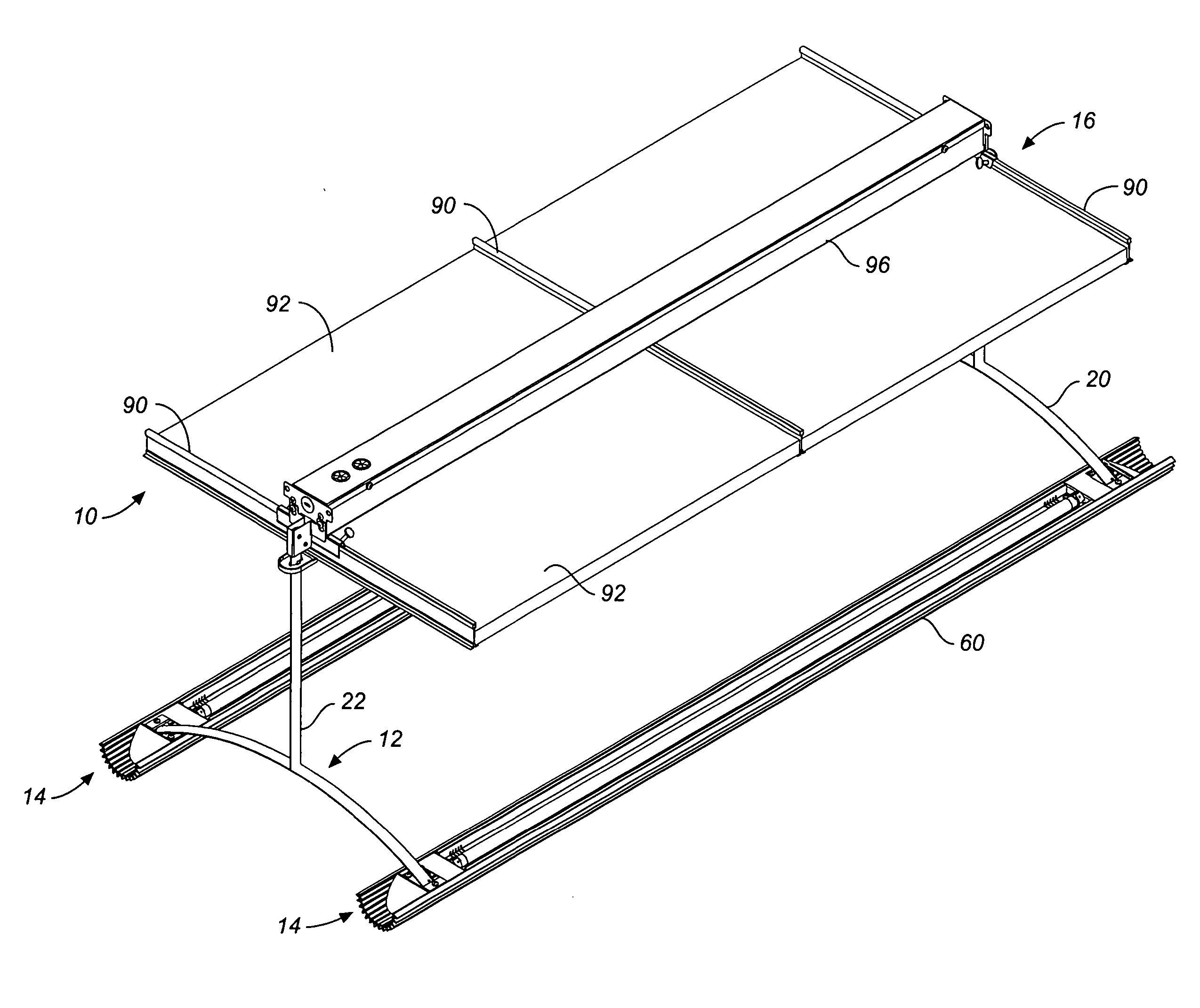
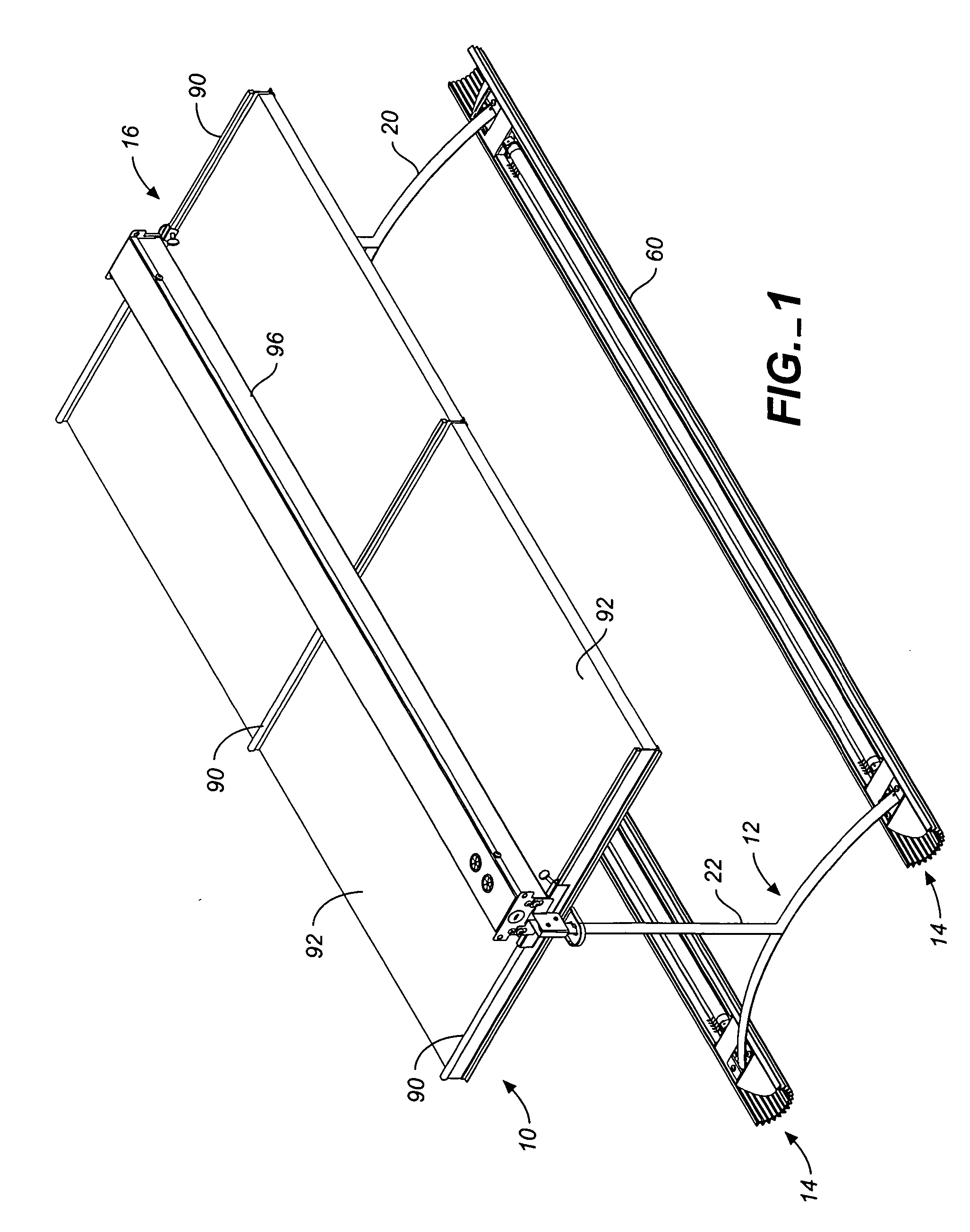
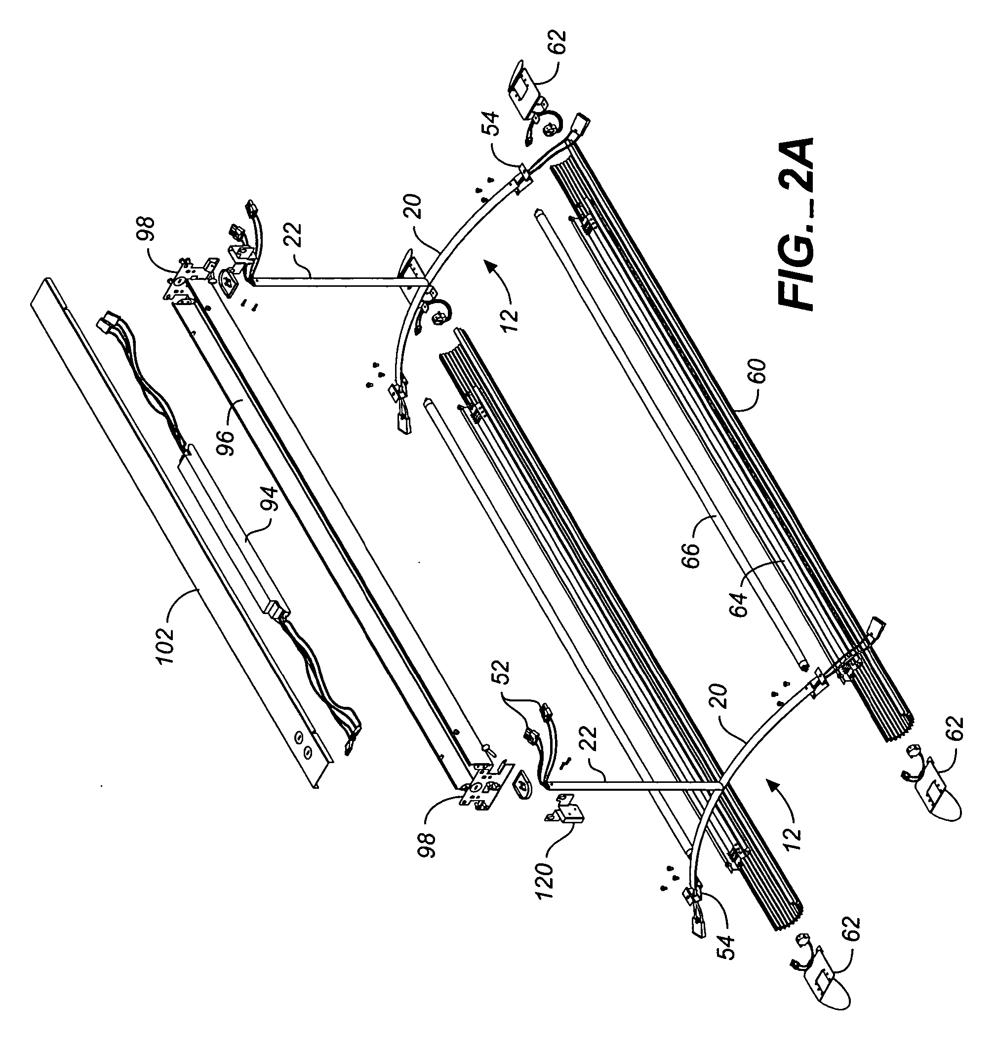
[0005] An approved small profile hanger system for ceiling suspended lighting fixtures comprises a plurality of hanger assemblies, each hanger assembly including a vertical support stem and a downwardly arced cross bar. A bottom portion of the support stem is secured to the apex of the cross bar. The support stem and cross bar have a common profile comprising two half sections, each half section having a generally elliptical shape, together generally resembling a “cat's eye” shape. Two pairs of wire holes extend through the entire length of both the support stem and cross bar. The wire holes are generally aligned along the wider dimension of the profile of the stem and cross bar. Each pair of holes consists of an inside and outside hole. The inside and outside holes overlap, forming an intermediate gap narrower than the dimension of either of the holes. Each hole is sized to receive an insulated wire, such as an 18 gauge insulated lamp wire. The narrowness of the intermediate gap is such that any wire being fed through one of the wire holes is prevented from crossing over into the other wire hole. Preferably, the inside hole is slightly smaller than the outside hole, the combination of the reduced hole size and intermediate gap still providing adequate room for feeding wires into the wire holes. The reduced hole size has the advantage of a corresponding increase in material of the stem and cross bar, increasing the strength of the stem and cross bar. A center bore also extends through the entire length of the stem and cross bar to lighten these elements.
[0008] The improved hanger system is light-weight, has a relatively small profile, provides a hidden wiring passage for extending wiring from the ballast assembly above the ceiling to the lamp in the diffuser housing, and the entire system is easy to assemble. Preferably the hanger elements are constructed of extruded aluminum.

Problems solved by technology

Such fixtures are typically suspended by steel aircraft cable or rigid hollow stems, and would have relatively bulky power cords that would have to be run up through the ceiling for connection to an electrical junction box.
While stems have the advantage that they hide the power cord, they are themselves relatively large in diameter and do not contribute to an aesthetically pleasing hanger system, and particularly hanger systems having small profiles.

Method used


Image

  • Small profile hanger system for ceiling suspended lighting fixtures
  • Small profile hanger system for ceiling suspended lighting fixtures
  • Small profile hanger system for ceiling suspended lighting fixtures

Examples


Embodiment Construction

[0009]FIG. 1 is a top perspective view of a lighting assembly comprised of small profile indirect lighting fixtures and a hanger system in accordance with the invention for suspending the lighting assembly below a grid ceiling system.

[0010]FIG. 2A is an exploded view thereof.

[0011]FIG. 2B is an exploded fragmentary view thereof showing in greater detail the connection of the hanger system of the invention to one of the lighting fixtures of the assembly.

[0012]FIG. 2C is a fragmentary view of the portion of the assembly shown in FIG. 2B fully assembled.

[0013]FIG. 2D is a cross-sectional view of one of the lighting fixtures suspended by the hanger system of the invention as shown in FIG. 1.

[0014]FIG. 3 is an end elevational view of the small profile indirect lighting fixtures and a hanger system shown in FIG. 1.

[0015]FIG. 4 is a side elevational view thereof.

[0016]FIG. 5 is a top perspective view, partially cut-away, of one of the hangers for the indirect lighting fixtures shown...


PUM


Abstract

An improved small profile hanger system for ceiling suspended lighting fixtures comprises a plurality of hanger assemblies having a support stem and a downwardly arced crossbar. The support stem and crossbar have a relatively small elliptical profile have two sets of wire holes, each set of wire holes having an inner hole and an outer hole overlapping the inner hole, the inner and outer holes defining an intervening gap narrower than the dimension of either hole. The holes are sized to receive an insulated wire; the intervening gap preventing the wire from crossing over into the adjacent hole. The wire holes of the support stem are in communication with the wire holes of the crossbar providing a fully enclosed wiring passage from a ballast box assembly installed above a suspended ceiling to energize a lamp in a diffuser depending from a pair of the crossbars.

Description

CROSS-REFERENCE TO RELATED APPLICATIONS [0001] This application claims the benefit of U.S. Provisional Application No. 60 / 579,042, filed Jun. 10, 2004.BACKGROUND OF THE INVENTION [0002] The present invention relates to lighting fixture hanger systems and particularly hanger systems for small profile ceiling suspended lighting fixtures. [0003] Lighting for interior architectural spaces is often provided by lighting fixtures suspended from overhead ceiling structures. Examples of ceiling suspended architectural lighting fixtures include linear fluorescent fixtures comprised of linear fixture housings having a uniform cross-sectional shape. Such fixtures are typically suspended by steel aircraft cable or rigid hollow stems, and would have relatively bulky power cords that would have to be run up through the ceiling for connection to an electrical junction box. Where fixtures are suspended by aircraft cable, the power cord for each fixture would normally be run up and sometimes wrap aro...

Claims


Application Information

Patent Timeline
Patent Type & Authority Applications(United States)
IPC IPC(8): E04B9/00F21S2/00F21S8/06F21V3/00F21V7/00F21V17/16F21V21/02F21V21/112F21V21/116F21V21/34F21V23/02F21V27/00
CPCE04B9/006F21S2/00F21S8/06F21V3/00F21V7/0016F21V17/16F21Y2103/00F21V21/112F21V21/116F21V21/34F21V23/026F21V27/00F21V21/02
Inventor TRAN, MICHAEL TRUNGLY, HUE
Owner ABL IP HLDG
Learn More