Device for separating the epithelial layer from the surface of the cornea of an eye

a technology of epithelial layer and eye, which is applied in the field of eye surgery, eye treatment, eye implants, etc., can solve the problems of permanent degrading visual performance, poor quality of procedure and healing time, and use of microkeratomes, so as to reduce the visual rehabilitation period and postoperative pain

Inactive Publication Date: 2005-12-29
SIGHTRATE
View PDF99 Cites 14 Cited by
  • Summary
  • Abstract
  • Description
  • Claims
  • Application Information

AI Technical Summary

Benefits of technology

[0012] Each of the above aspects provides the advantage of reducing the visual rehabili...

Problems solved by technology

It is important that the knife used during the LASIK procedure is sharp, otherwise the quality of the procedure and the healing time are poor.
There are some complications related to the use of microkeratomes.
These complications represent irregular incisions of the cornea, a situation that can permanently degrade visual performance.
A drawback of PRK, however, i...

Method used


Image

  • Device for separating the epithelial layer from the surface of the cornea of an eye
  • Device for separating the epithelial layer from the surface of the cornea of an eye
  • Device for separating the epithelial layer from the surface of the cornea of an eye

Examples


second embodiment

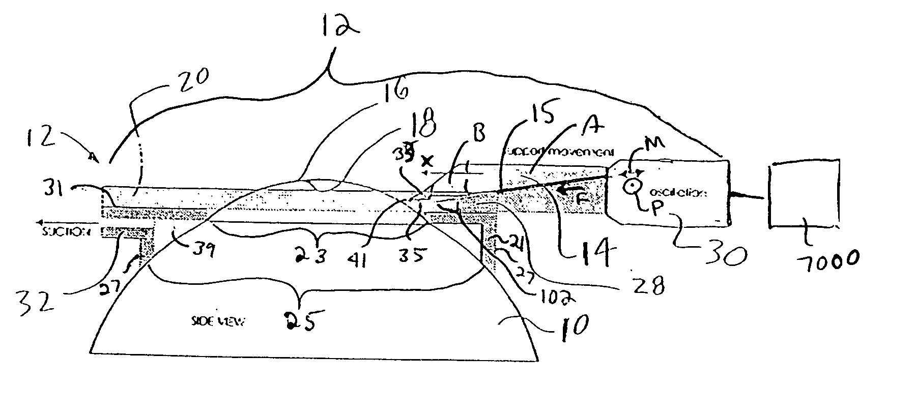
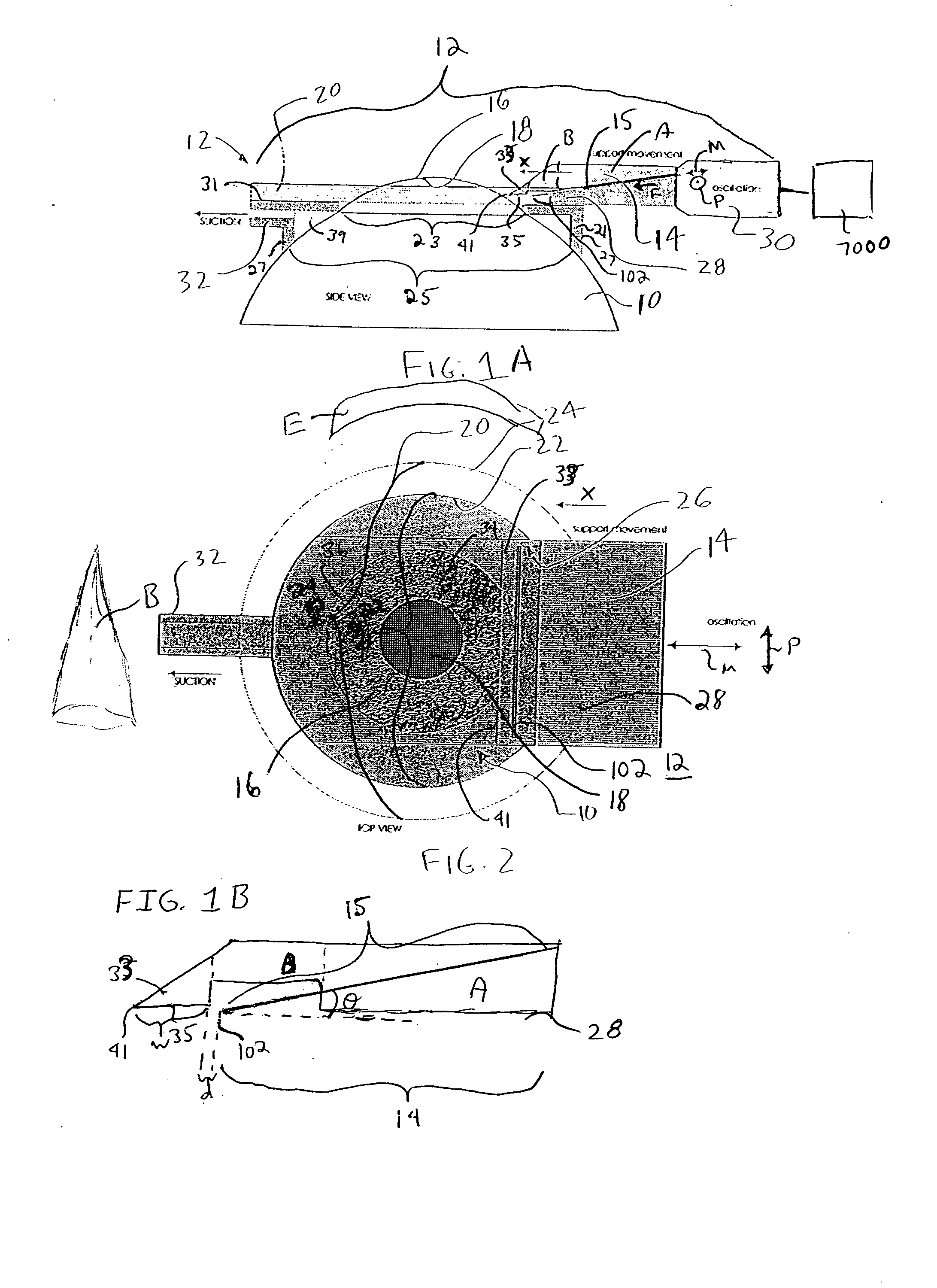
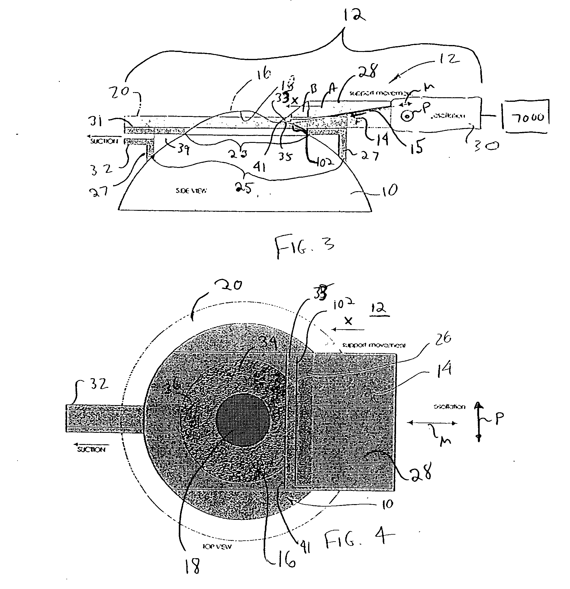
[0093]FIG. 22 is a diagram showing a side view of a leading edge 2100′ that can be used with a plate 15″. The plate 15″ is similar in structure with the plate 15 of FIGS. 1-9, except that it uses the leading edge 2100′. The plate 15″ is supported by separator support 28 so that the plate 15″ and separator support 28 define another embodiment of a separator to replace the separator 14 of FIG. 1. The plate 15″ is moved by oscillation device 30 in the same manner as plate 15 as described previously with respect to FIGS. 1-9. During the removal of the epithelial layer 16, the bottom planar surface 3000′ of the plate 15″ is positioned adjacent and parallel to the cornea underlying the Basal membrane 1900 (if it exists) while the leading edge 2100′ contacts the layer 16. Such an orientation is inherent in order to avoid cutting of the Basal membrane 1900 or cornea stroma. Accordingly, the leading edge 2100′, the top surface 3002′ and the bottom surface 3000′ can be treated together as def...

third embodiment

[0094]FIG. 23 is a diagram showing a side view of a leading edge 2100″ that can be used with a plate 15′″. The plate 15′″ is similar in structure with the plate 15 of FIGS. 1-9, except that it uses the leading edge 2100″. The plate 15′″ is supported by separator support 28 so that the plate 15′″ and separator support 28 define another embodiment of a separator to replace the separator 14 of FIG. 1. The plate 15′″ is moved by oscillation device 30 in the same manner as plate 15 as described previously with respect to FIGS. 1-9. During the removal of the epithelial layer 16, the bottom planar surface 3000″ of the plate 15′″ is positioned adjacent and parallel to the cornea underlying the Basal membrane 1900 (if it exists) while the leading edge 2100″ contacts the layer 16. Such an orientation is inherent in order to avoid cutting of the Basal membrane 1900 or cornea stroma. Accordingly, the leading edge 2100″ and the bottom surface 3000″ can be treated together as defining a blunt edg...


PUM


Abstract

A separator that includes a body and a leading edge portion. The leading edge portion includes an upper planar surface oriented at an angle ranging from approximately 40° to 90° relative to a horizontal plane and a lower planar surface oriented at an angle ranging from approximately 0° to 30° relative to the horizontal plane, wherein the upper planar surface and the lower planar surface intersect one another so as to define a blunt leading edge and the leading edge portion is made of a material that has a hardness so as to separate an epithelial layer of an eye from an cornea stroma of said eye without substantially damaging said epithelial layer and wherein said blunt leading edge is incapable of cutting said stroma.

Description

REFERENCE TO EARLIER FILED APPLICATIONS [0001] Applicants claim, under 35 U.S.C. § 119(e), the benefit of priority of the filing date of Aug. 6, 2004, of a U.S. Provisional Patent Application filed on the aforementioned date having the title “Separator for Corneal Epithelium” listing Scott M. Hampton, Stephen Woods and Harilaos Ginis as inventors and having an attorney docket no. of 2N04.1-040, the entire contents of which are incorporated herein by reference and in addition the present application is a continuation-in-part application of U.S. patent application Ser. No. 10 / 098,167, filed on Mar. 12, 2002, which is a continuation-in-part application of U.S. patent application Ser. No. 09 / 911,356, filed Jul. 23, 2001, the entire contents of each of which are incorporated by reference herein.BACKGROUND [0002] LASIK (Laser-Assisted In Situ Keratomileusis) is a surgical procedure intended to reduce a person's dependency on glasses or contact lenses. LASIK permanently changes the shape o...

Claims


Application Information

Patent Timeline
IPC IPC(8): A61F9/007A61F2/14A61F9/013
CPCA61F2/14A61F9/0133A61F9/013
Inventor PALLIKARIS, IOANNIS G.GINIS, HARILAOSHAMPTON, SCOTT M.WOODS, STEPHEN P.
Owner SIGHTRATE
Why Eureka
Try Eureka