
Program for calculating displacement of fluid and method for acquiring variables

Inactive Publication Date: 2005-12-29
CANON KK
View PDF5 Cites 8 Cited by
  • Summary
  • Abstract
  • Description
  • Claims
  • Application Information

AI Technical Summary

Benefits of technology

[0011] This invention has been achieved in the light of the above-mentioned problems associated with the prior art, and it is an object of the invention to provide a unified calculation method for calculating the compressible / incompressible fluid and the structure and a design analysis system, employing an existent elastic body solver, in which the setup of variables and boundary conditions is simple, the use memory is saved, the coding is easily made, and stable calculation is realized.
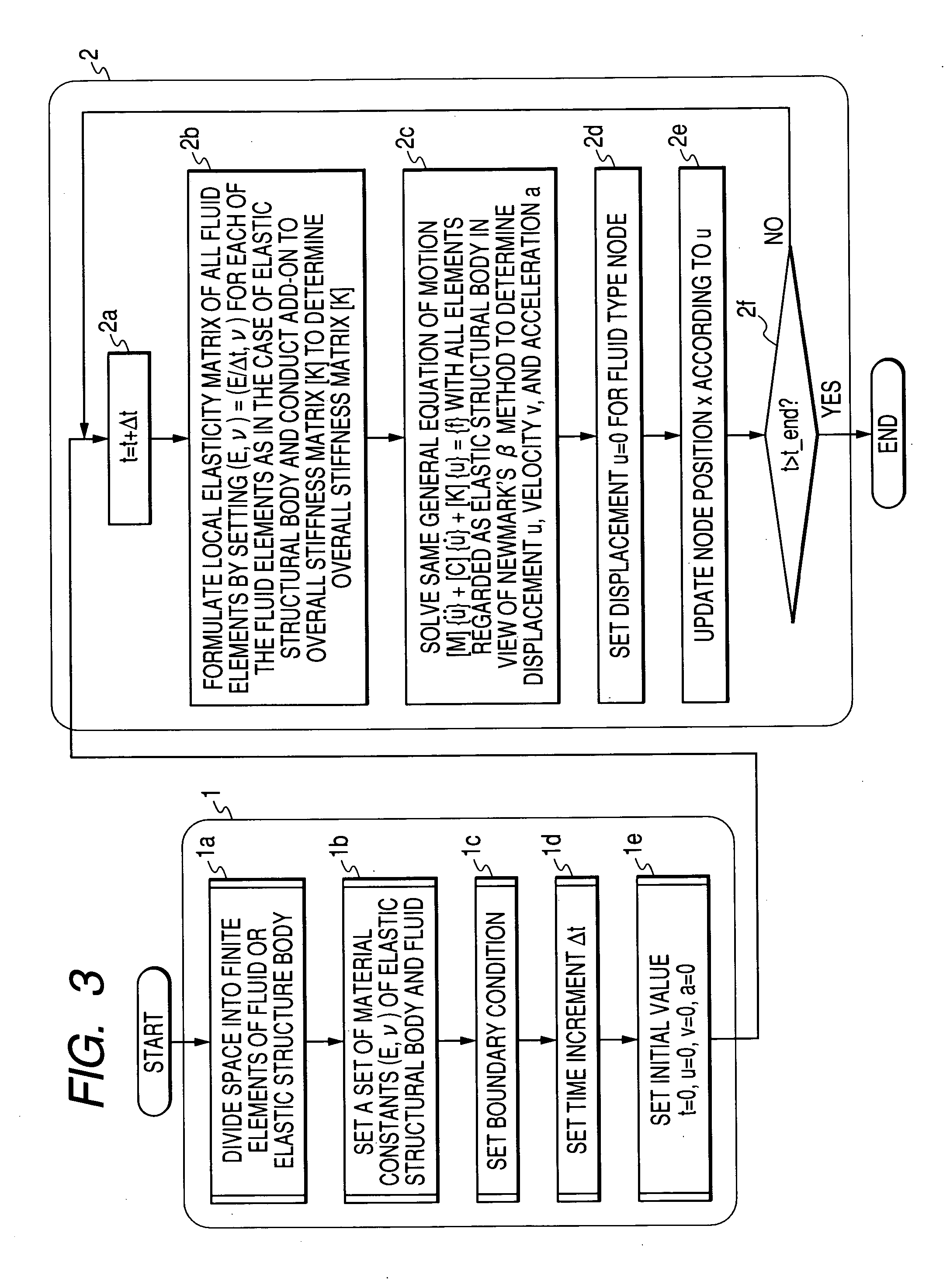
[0016] Moreover, the invention provides a calculation method comprises a step of transforming the physical property data of said fluid into structural body data where the fluid is regarded as an elastic body for a short period of time with means for inputting fluid data, a step of feeding said structural body data to an external structure calculation solver and executing a structure calculation, and a step of updating the variables and resetting the displacement of the fluid.

Problems solved by technology

As described above, the conventional fluid-structure coupling calculation method had the problem that the weak coupling method is sought for stability, and the strong coupling method is complex in the coding and has many variables.
Also, the extension of the strong coupling method to the compressible fluid is difficult.

Method used


Image

  • Program for calculating displacement of fluid and method for acquiring variables
  • Program for calculating displacement of fluid and method for acquiring variables
  • Program for calculating displacement of fluid and method for acquiring variables

Examples


embodiment 1

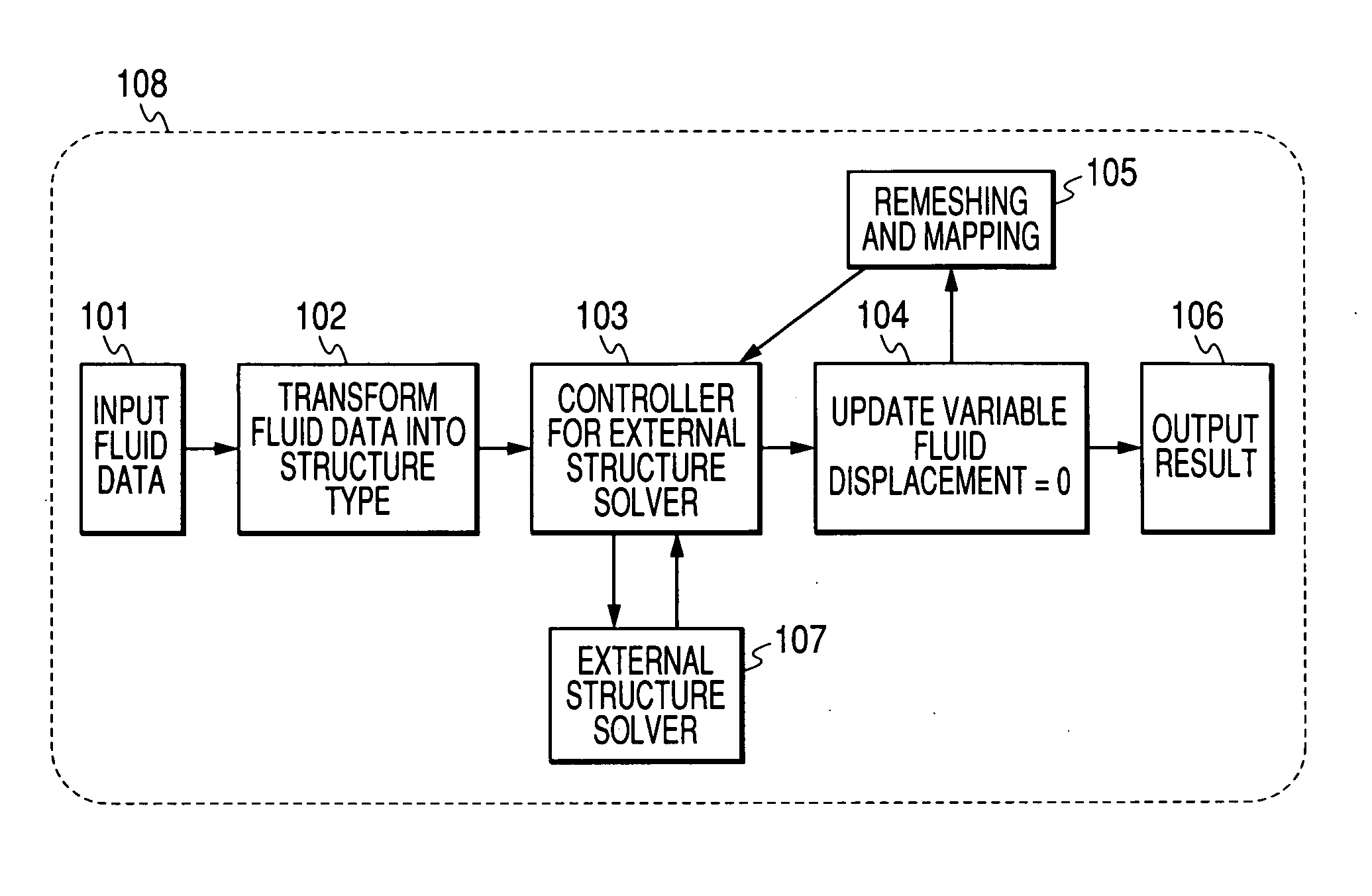
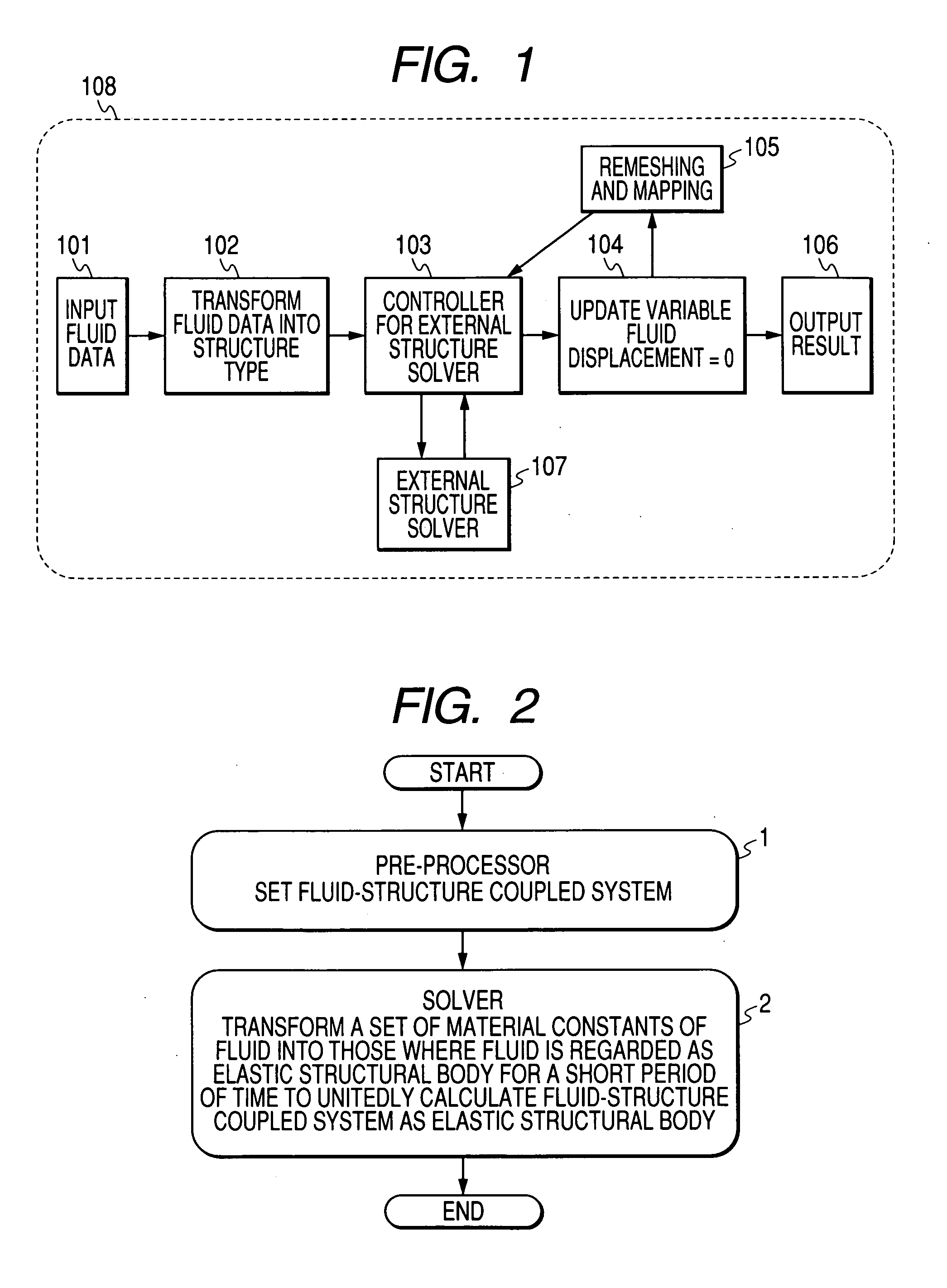
[0043]FIG. 1 is a diagram showing the features of the present invention. Reference numeral 101 designates means for inputting fluid data, 102 designates means for transforming physical property data of fluid into structural data where the fluid is regarded as an elastic body for a short period of time, 103 designates means for feeding data to an external structure calculation solver to perform structure calculation, 104 designates means for updating variables and resetting the displacement of fluid, 105 designates means for remeshing and mapping, 106 designates means for outputting the results, and 108 designates a design analysis system of the invention, comprising the means 101 to 106. Also, reference numeral 107 designates an external structure solver.

[0044] That is, the invention provides a unified calculation method for the compressible / incompressible fluid and the structure and a design analysis system, comprising means for inputting fluid data, means for transforming fluid p...

embodiment 2

[0086]FIG. 8 is a block diagram showing the features of an embodiment 2. The embodiment 2 is almost equivalent to the embodiment 1, except for means 201 for inputting mixture data of fluid and elastic body.

[0087] That is, in the embodiment 2, a design analysis system comprising means for inputting mixture data of fluid and elastic body, means 102 for transforming material data of the fluid into structural body data, means 103 for feeding data to an external structure calculation solver to perform structure calculation, and means 104 for updating variables and resetting the displacement of fluid.

[0088] The embodiment 2 is a design analysis system employing a design analysis method for performing calculation wherein the fluid is regarded as a structural body for a short period of time, in which coupled calculation of fluid and elastic body is performed employing an external elastic body solver with means for inputting mixture data of fluid and elastic body.

[0089]FIG. 9 shows one ex...

embodiment 3

[0091]FIG. 10 is a diagram showing the features of an embodiment 2. Reference numeral 101 designates a remeshing and mapping process.

[0092] The embodiment 3 particularly involves conducting new meshing (remeshing process) after updating the node position in accordance with the displacement, interpolating the physical quantity of original nodes and setting (mapping process) it as the physical quantity of new nodes. There is the effect that the fluid and structure calculation for large deformation is performed by remeshing and mapping after updating the node position in accordance with the displacement.


PUM


Abstract

Disclosed herein is a program for calculating a displacement of a fluid comprising calculating the displacement with the fluid regarded as an elastic structural body for a given period of time.

Description

BACKGROUND OF THE INVENTION [0001] 1. Field of the Invention [0002] The present invention relates to a numerical value calculation method and a design analysis system that are applied to the design and analysis of MEMS (Micro Electro Mechanical Systems) devices and NEMS (Nano Electro Mechanical Systems) devices, and more particularly, to a unified method of calculating gas, liquid and solid compression or non-compression, which is superior in the coupled calculation with an elastic structural body, and a design analysis system. [0003] 2. Related Background Art [0004] Recently, there is an increasing demand for the CAD apparatus which makes the design analysis of devices applying nano-technology such as a MEMS device or NEMS device, along with the development of the solid micro-machining technology. In such CAD apparatus, it is important that the integrated analysis and design can be made always easily by many physics such as light, electromagnetism, electrostatics, elasticity, fluid...

Claims


Application Information

Patent Timeline
IPC IPC(8): B01L3/00G01N11/02G06F19/00
CPCB01L3/50273B01L2400/0487B01L2200/143B01L2200/12
Inventor SUGIOKA, HIDEYUKI
Owner CANON KK
Learn More