
Replication system having the capability to accept commands at a standby-system site before completion of updating thereof

a technology of a standby system and a command, applied in the field of replication systems, can solve the problems of rapid switching, increase in processing amount, performance drop, etc., and achieve the effect of reducing performance drop

Inactive Publication Date: 2005-12-29
NEC CORP
View PDF4 Cites 37 Cited by
  • Summary
  • Abstract
  • Description
  • Claims
  • Application Information

AI Technical Summary

Benefits of technology

[0015] It is an object of the present invention to provide a replication system that, upon the occurrence of a problem, rapidly switches from a normal-system site to a standby-system site and reliably continues functions, and moreover, that reduces drops in performance. The replication system of the present invention further includes a first site, a second site, and a transfer device.

Problems solved by technology

However, the above-described technology has the following problems:
In the replication system of the prior art, however, synchronous or asynchronous replication from the normal-system site to the standby-system site takes time, and rapid switching was therefore problematic when switching after updating the data of the standby-system site.
However, such a procedure causes drops in performance such as an increase in the amount of processing and a reduction in throughput.
In addition, when a logical error occurs in the normal-system site, the replication process may cause the logical error to be reproduced in the standby-system site, preventing normal operation despite the switch to the standby-system site.
However, data of high importance are in some cases not protected in replication systems of the prior art.

Method used


Image

  • Replication system having the capability to accept commands at a standby-system site before completion of updating thereof
  • Replication system having the capability to accept commands at a standby-system site before completion of updating thereof
  • Replication system having the capability to accept commands at a standby-system site before completion of updating thereof

Examples


first embodiment

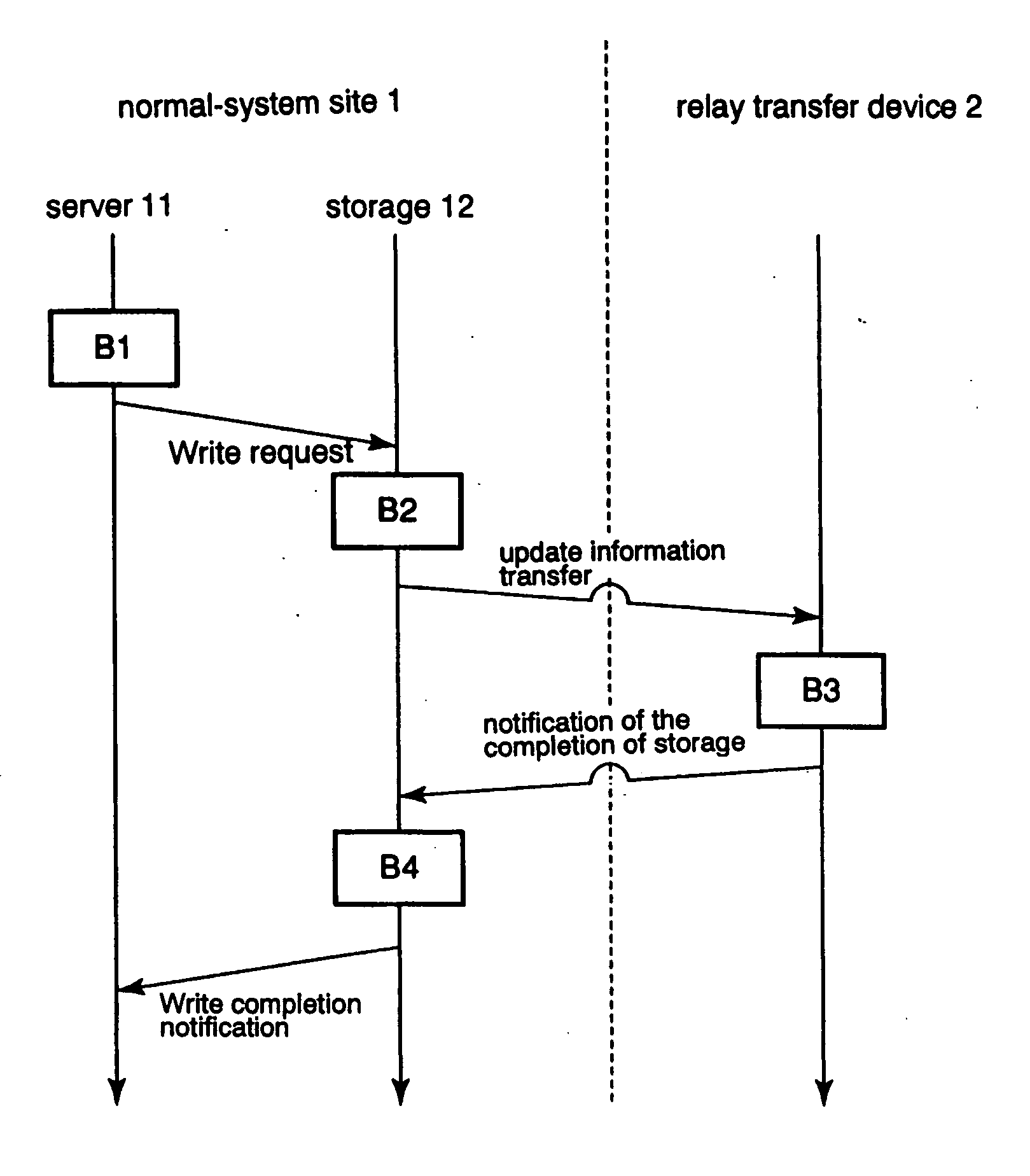
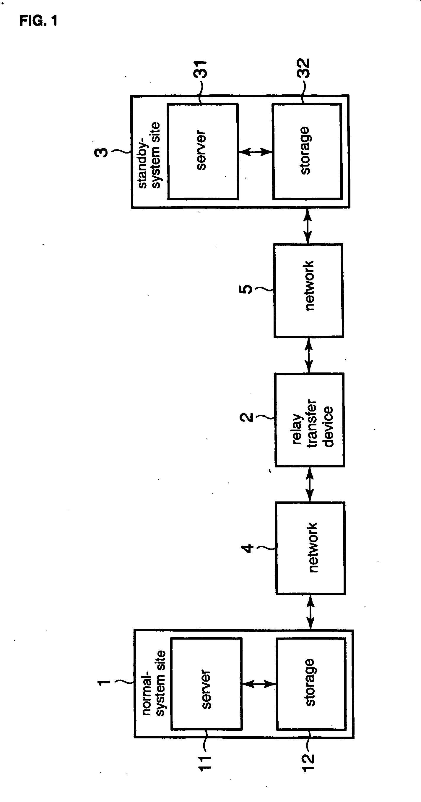
[0080]FIG. 1 is a block diagram showing the replication system of the first embodiment of the present invention. The replication system of the first embodiment is a computer system that provides services and that includes normal-system site 1, standby-system site 3, and relay transfer device 2. Normal-system site 1 and relay transfer device 2 are connected by network 4; and standby-system site 3 and relay transfer device 2 are connected by network 5.

[0081] Normal-system site 1 is the site that is used during normal operation and includes server 11 and storage unit 12.

[0082] Storage 12 is a memory device for storing data. As an example, storage 12 may be a single disk device or a disk array device that is composed of a plurality of disk devices. As another example, storage 12 may be a magneto-optical device or an array device that is a collection of such devices. As yet another example, storage 12 may be a memory device that is realized by a single or a plurality of semiconductor m...

second embodiment

[0235] The second embodiment of the present invention is a system in which, when there is a plurality of types of data, a transfer priority is assigned to each data type in accordance with a fixed policy, and data are then transferred from relay transfer device 2 to standby-system site 3 in accordance with the transfer priority. This form can be widely applied, including in the first embodiment and in Modifications 18 of the first embodiment. An example is here shown in which this form is applied to the first embodiment.

[0236]FIG. 40 is a block diagram showing the configuration of the replication system of the second embodiment. Referring to FIG. 40, the replication system of the second embodiment includes normal-system site 1, relay transfer device 2, standby-system site 3, and networks 4 and 5, as in the first embodiment. In addition, normal-system site 1 includes server 11 and storage 12. Standby-system site 3 includes server 31 and storage 32.

[0237] In the second embodiment, s...

modification 1

of the Second Embodiment

[0259] Modification 1 of the second embodiment is a form that allows alteration of the data transfer policy of relay transfer device 2.

[0260]FIG. 46 is a block diagram showing the configuration of the replication system in Modification 1 of the second embodiment. Referring to FIG. 46, the replication system of the present modification includes policy control device 6 in addition to normal-system site 1, relay transfer device 2, standby-system site 3, and networks 4 and 5. Normal-system site 1, relay transfer device 2, standby-system site 3, and networks 4 and 5 are all equivalent to the second embodiment shown in FIG. 40.

[0261] Policy control device 6 supplies instructions to relay transfer device 2 for controlling the policy of policy storage unit 206 of relay transfer device 2 during operation or during a halt in operation. For example, policy control device 6 detects the states of normal-system site 1, relay transfer device 2, standby-system site 3 or ot...


PUM


Abstract

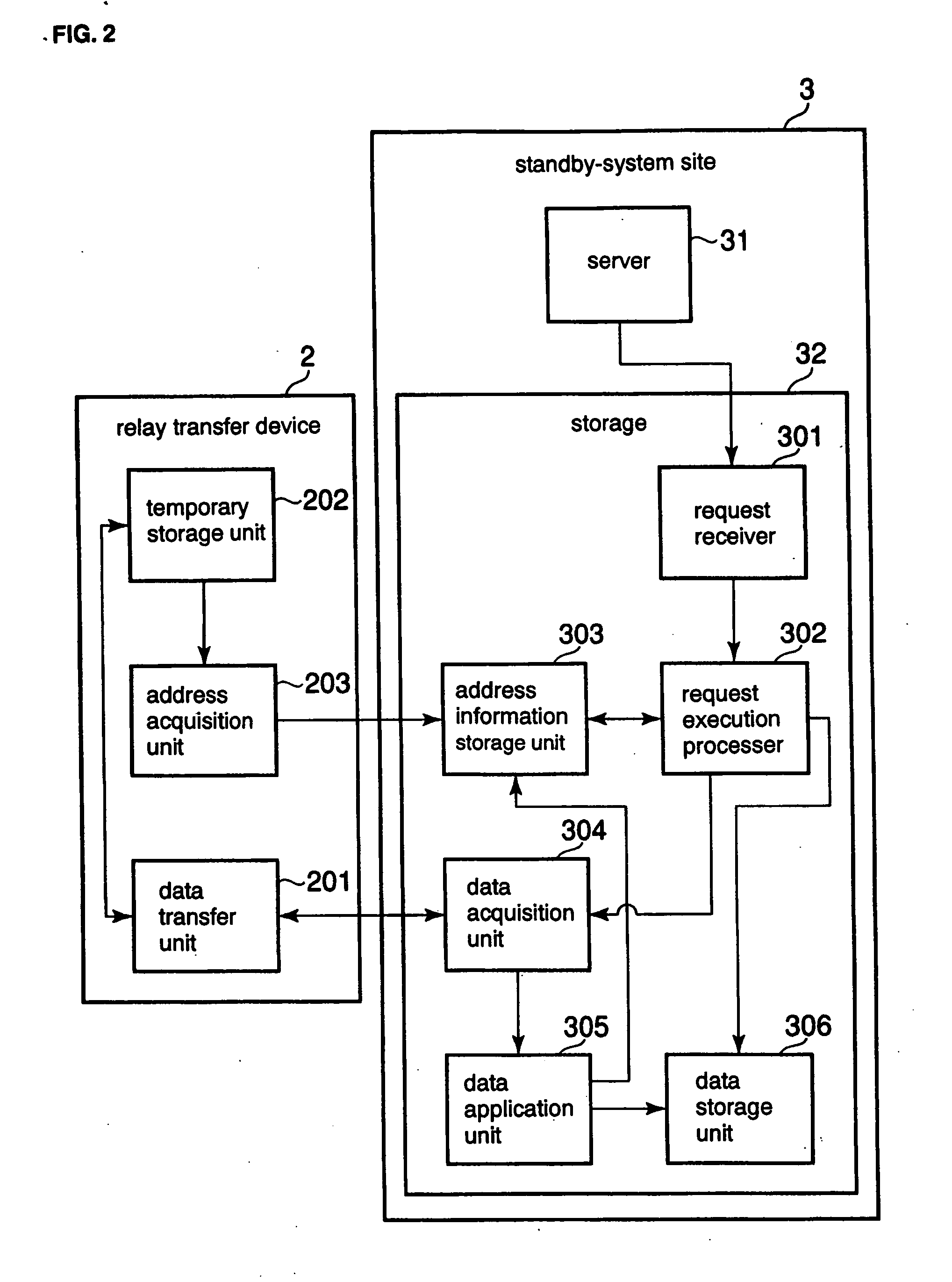
A replication system rapidly switches from a normal-system site to a standby-system site in the event of a problem and reliably maintains functions, and moreover, reduces drops in performance. A first site provides system functions that accompany writing and reading of data. A relay transfer device receives update information from the first site, causes completion of processes for replication in the first site, and continuously executes processes for successively transferring the update information to a second site. The second site receives the update information of the first site and applies this update information to itself to retain a replica of the data of the first site. If, when executing a write request command or a read request command to provide at least a portion of the system functions, the second site has not yet retained the most recent data that are the target of the command, the second site acquires the necessary update information and then executes the command.

Description

BACKGROUND OF THE INVENTION [0001] 1. Field of the Invention [0002] The present invention relates to a replication system for implementing replication between a normal-system site and a standby-system site. [0003] 2. Description of the Related Art [0004] Conventionally, computer systems have been used that are provided with a normal-system site (or an operating system site) and a standby-system site for maintaining functions even in the event of a disaster, such computer systems being referred to as “replication systems.” For example, the normal-system site normally operates to provide system functions, and the standby-system site operates in place of the normal-system site when the normal-system site is unable to operate normally. [0005] In order to provide the functions of a computer system, the normal-system site and standby-system site each have storage unit for storing data. In a replication system, the data in the storage of the normal-system site are replicated and retained i...

Claims


Application Information

Patent Timeline
IPC IPC(8): G06F12/00
CPCG06F11/2023G06F11/2097G06F11/2048G06F11/2038
Inventor KAN, MASAKIYAMATO, JUN-ICHIKANEKO, YUJI
Owner NEC CORP
Learn More