
Concealable zipper slider structure

a zipper slider and zipper technology, applied in the direction of slide fasteners, snap fasteners, press-button fasteners, etc., can solve the problems of zipper slider and nose parts, high manufacturing costs of zipper sliders, and inability to permit variety in aesthetic appearance, so as to reduce manufacturing costs, simplify the molding of zipper sliders, and automate the manufacturing of zipper sliders according to inventions

Active Publication Date: 2006-01-05
LIN YU PAU
View PDF14 Cites 18 Cited by
  • Summary
  • Abstract
  • Description
  • Claims
  • Application Information

AI Technical Summary

Benefits of technology

[0009] It is therefore an object of the invention to provide a concealable zipper slider structure that is formed by securely assembling separate slider body and nose part. The manufacture of the zipper slider according to the invention can be automated, molding of the zipper slider can be simplified and its manufacturing cost reduced.
[0010] It is another object of the invention to provide a zipper slider that allows the use of different materials and different colors for the slider body and the nose part to improve the aesthetic aspect of the zipper slider.
[0013] The design of the zipper slider by assembly of separate slider body and nose part simplifies the mold for the same and reduces the cost thereof. In addition, the slider body and the nose part can be made of different materials and different colors to improve the aesthetic appearance of the zipper slider.

Problems solved by technology

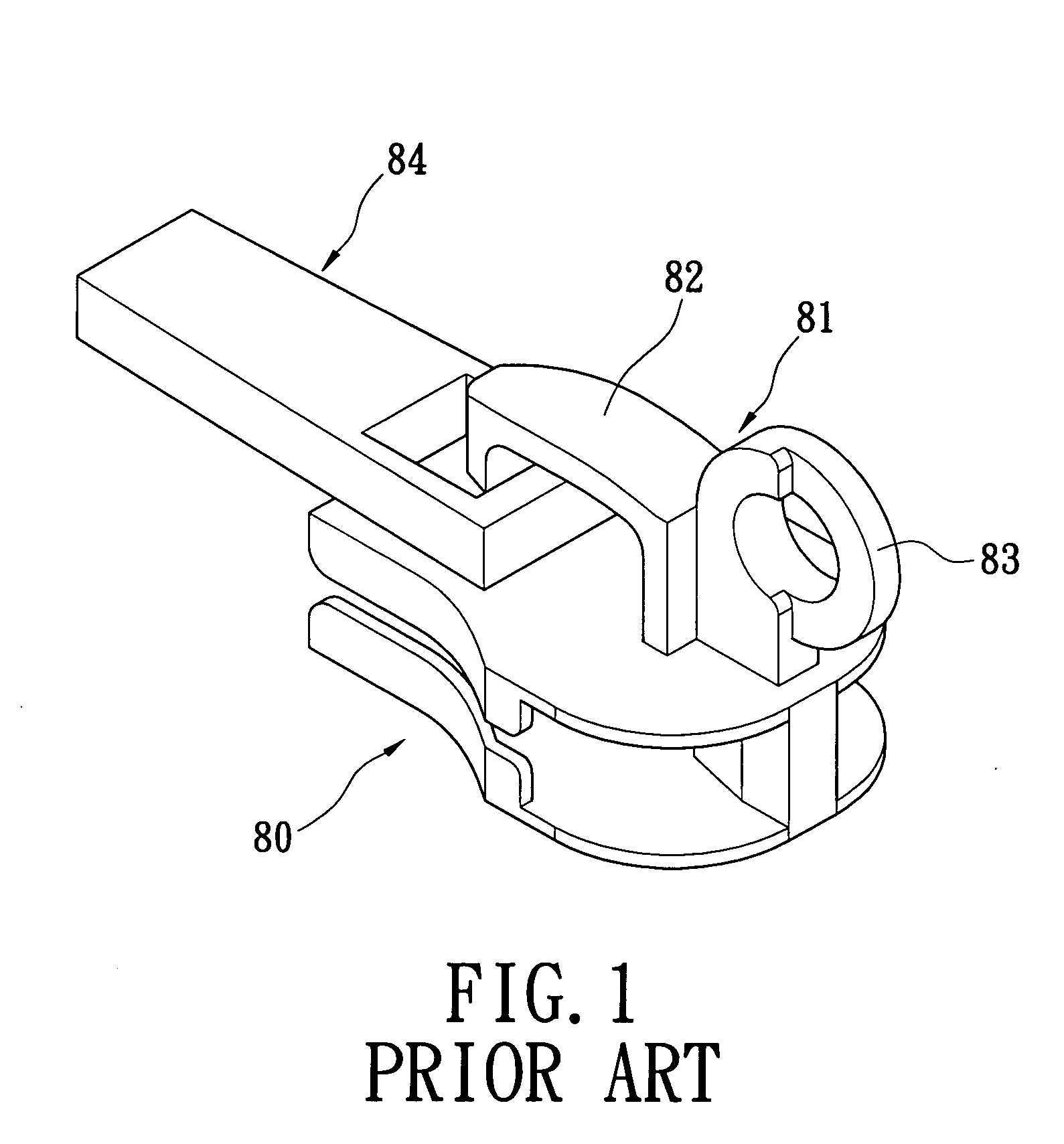
Unfortunately, the conventional design of the slider body and nose part in a one integral piece results in a complex structure of the zipper slider, which requires a complex mold design and results in a higher manufacturing cost of the zipper slider.
The design in a single body further limits the zipper slider and nose part to be made of a same material and color, which does not permit variety in the aesthetic appearance thereof.

Method used


Image

  • Concealable zipper slider structure
  • Concealable zipper slider structure
  • Concealable zipper slider structure

Examples


Embodiment Construction

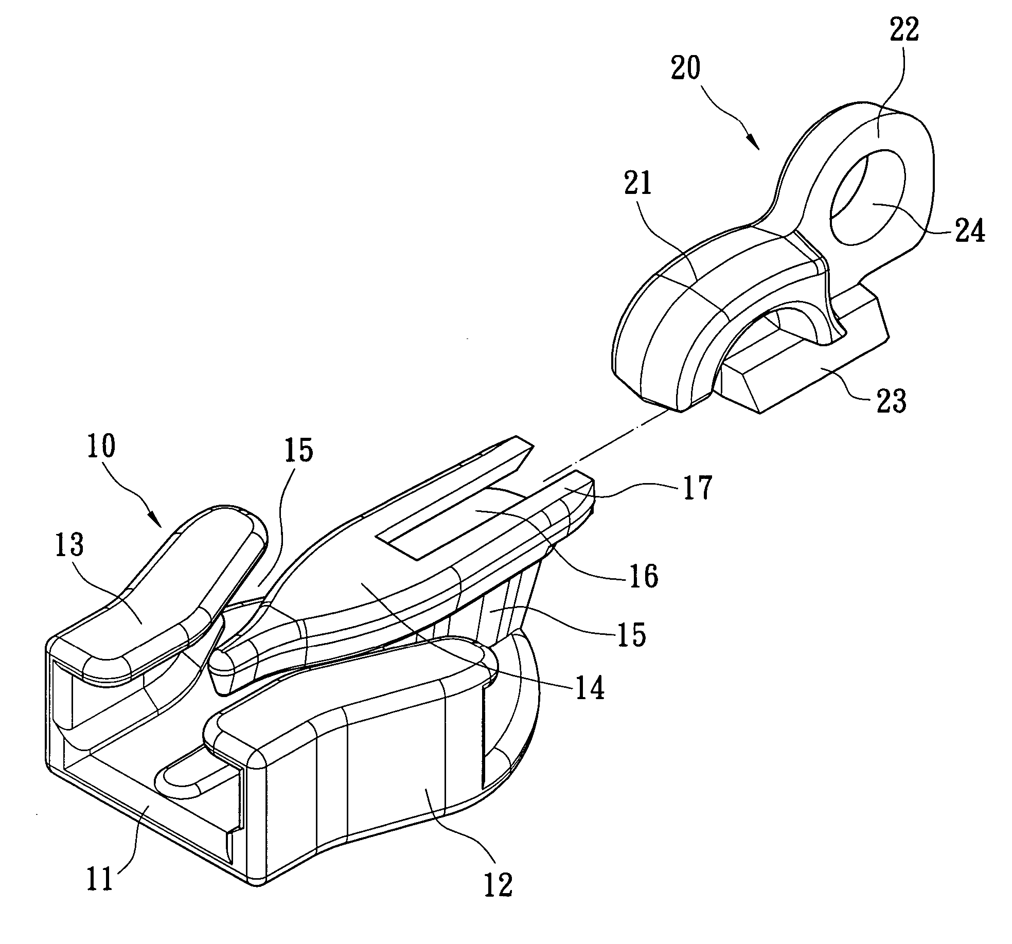
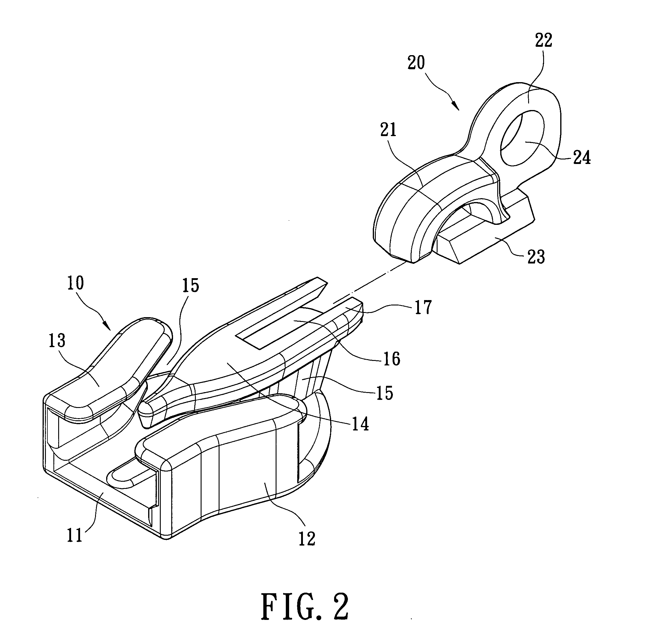
[0022] Referring to FIG. 2, FIG. 3 and FIG. 4, the invention provides a concealable zipper slider structure made of two component parts. The zipper slider includes a slider body 10 and a nose part 20. The slider body 10 has a bottom part 11 with arcuate peripheral edges. Lateral ribs 12 extend upward at an adequate height and in a single body from left and right sides of the bottom part 11. Upper ends of the lateral ribs 12 project horizontally inward to integrally form two top parts 13. The two top parts 13 lie over the bottom part 11 at a height, and are separated from each other by a gap.

[0023] A connecting portion 14 protrudes from the bottom part 11, and two sliding slits 15 are formed between the bottom part 11 and the two top parts. The two sliding slits 15 are located inside the slider body 10 at two sides of the connecting portion 14. The two sliding slits 15 can receive the two teeth tapes of the zipper (not shown), so that the slider body 10 can be used to control zipper...


PUM


Abstract

A concealable zipper slider is described. The concealable zipper has a slider body with a bottom part, two lateral ribs and two top parts. A connecting portion protrudes from the bottom part, two sliding slits are formed between the bottom part and the two top parts at two sides of the connecting portion, and the connecting portion has dovetail slit. A nose part has a nose body and a dovetail base. The dovetail base of the nose part engages in the dovetail slit of the slider body. The zipper slider thereby is formed by assembly of separate slider body and nose part, which allows automated manufacture, reduces the manufacturing cost and permits variety in the aesthetic appearance thereof by the use of different materials and colors.

Description

BACKGROUND OF THE INVENTION [0001] 1. Field of the Invention [0002] The invention relates to a concealable zipper slider. More particularly, the invention relates to a zipper slider that is formed by assembly of separate slider body and nose part, which allows automated manufacture, reduces the manufacturing cost and permits variety in the aesthetic aspect appearance thereof by the use of different materials and colors. [0003] 2. Description of the Related Art [0004] Zipper sliders can be conventionally used on baggage zippers. The zipper slider can be provided with a tab that allows convenient pulling of the zipper slider to open or close the zipper. [0005] Referring to FIG. 1, a conventional concealable zipper slider includes a slider body 80 and a nose part 81. The nose part 81 is integrally connected with the slider body 80 in one piece, and has a nose body 82 pivotally mounted with the tab 84 for conveniently pulling the zipper slider. A locking ring 83 is further integrally co...

Claims


Application Information

Patent Timeline
IPC IPC(8): A44B19/26
CPCA44B19/26Y10T24/2561Y10T24/2588
Inventor LIN, YU-PAU
Owner LIN YU PAU
Learn More