Foundation shock eliminator

Inactive Publication Date: 2006-01-05
TSAI CHONG SHIEN
View PDF7 Cites 28 Cited by
  • Summary
  • Abstract
  • Description
  • Claims
  • Application Information

AI Technical Summary

Benefits of technology

[0012] The main objective of the invention is to provide a foundation shock eliminator that will efficiently dissipate both vertical and ho

Problems solved by technology

This can concern vibration and shocks from seismic events or even low intensity events such as subway trains passing below structures.
Although the subway train shocks are relatively predictable in their direction, intensity and even timing, the same is not true for earthquakes that can vary enormously, thereby providing particular difficulty to civil engineers.
Shocks, such as seismic shocks or low intensity shocks will influence adversely qualities of high precision electronic products during the fabrication of the electro

Method used


Image

  • Foundation shock eliminator
  • Foundation shock eliminator
  • Foundation shock eliminator

Examples


second embodiment

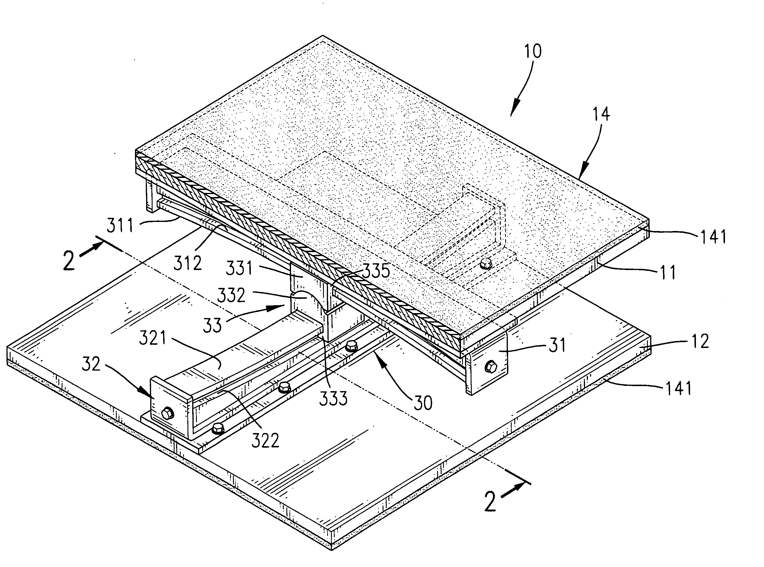
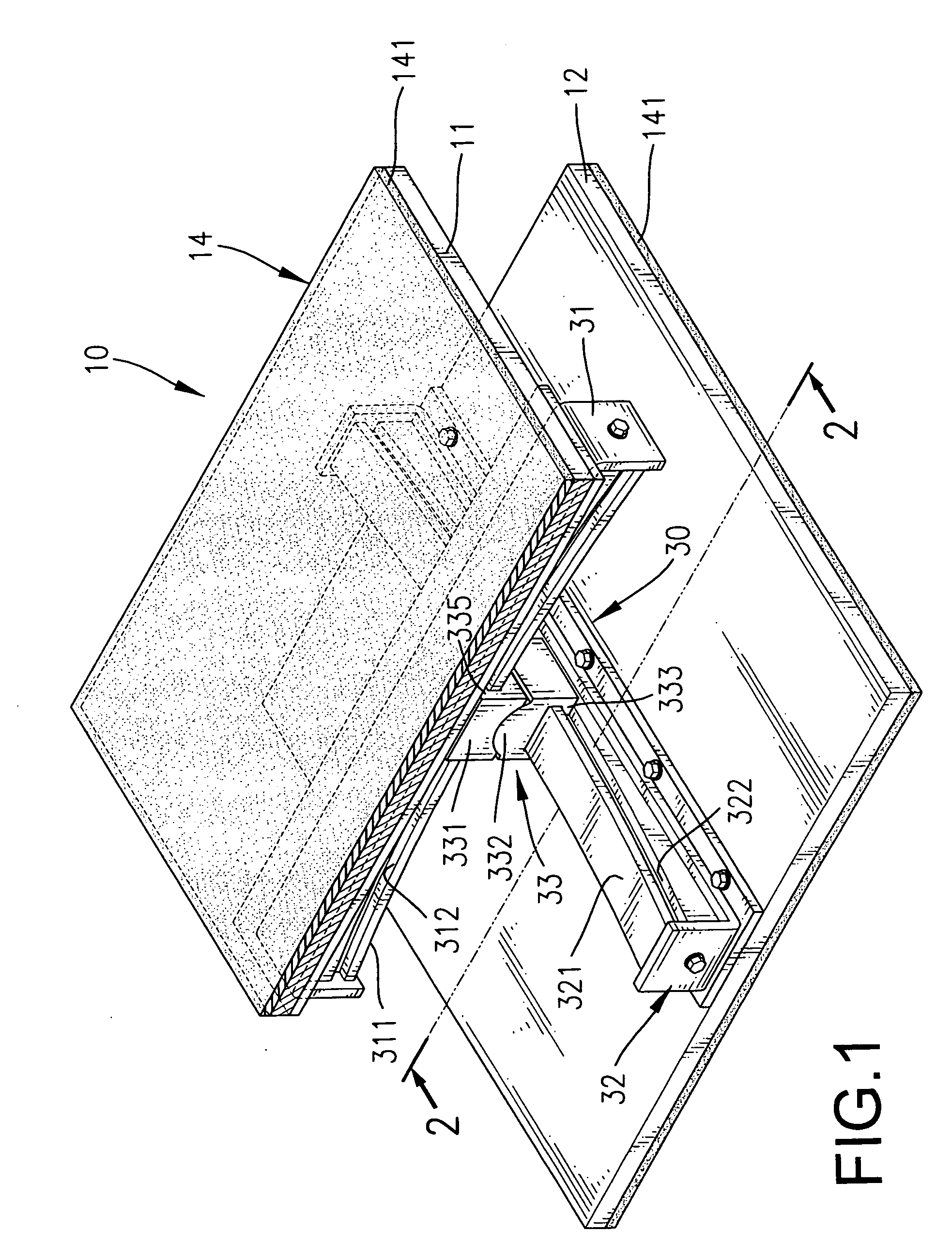
[0033] With reference to FIG. 3, a foundation shock eliminator in accordance with the present invention comprises an upper block (11), a lower stationary base (12), an interconnecting assembly (30′) and an energy damping coating (14′).

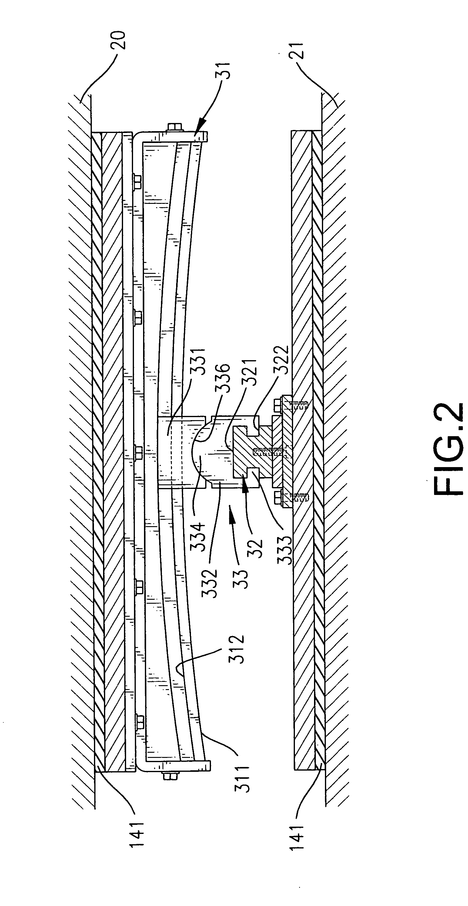
[0034] The interconnecting assembly (30′) comprises an upper track (31), a lower track (32) and a track joint (33′). The upper track (31) and the lower track (32) are arranged as previously described.

[0035] The track joint (33′) is slidably mounted between the upper track (31) and the lower track (32) and comprises an upper sliding block (331), a lower sliding block (332) and multiple first rollers (337).

[0036] The upper sliding block (331) and the lower sliding block (332) are configured as previously described. The upper track (31) has an upper concave surface (311). The lower track (32) has a lower concave surface (321). The first rollers (337) are respectively mounted between the upper concave surface (311) and the upper sliding block (331), and ...

first embodiment

[0041] The second roller (337′) is rotatably mounted between and is held in the concave recesses (338) and is a ball. The roller coating (142) covers around the second roller (337) as the energy damping coating (14) of the

fourth embodiment

[0042] With reference to FIG. 6, a fifth embodiment of the present invention modifies the fourth embodiment and further comprises multiple first rollers (337). The first rollers (337) roll respectively along the upper and the lower concave surfaces (311, 321) and can be cylinders or balls.

[0043] Consequently, when the shocks that are transmitted through the foundation shock eliminator (10) will be diminished, the upper block (11) moves relative to the lower stationary base (12) to counterbalance most horizontal shock effects because of relative motions between the tracks (31, 32) and the track joint (33, 33′, 33″, 33′″). In addition, the energy damping coating (14) will absorb the shock energy to cushion the structures or machines mounted on the foundation shock eliminator (10) and keeps the structures or machines from most vertical shocks. The foundation shock eliminator (10) in accordance with the present invention will stop the path of shock transmission at both horizontal and ve...


PUM


Abstract

A foundation shock eliminator includes an upper block, a lower stationary base, an interconnecting assembly and an energy damping coating. The lower stationary base is mounted under the upper block. The interconnecting assembly is mounted between the upper block and the lower stationary base and includes an upper track, a lower track and a track joint. The upper and the lower tracks are respectively attached to the upper block and the lower stationary base and are arranged in a cross. The track joint is slidably mounted between the tracks. The energy damping coating mounted in the foundation shock eliminator absorbs shock energy. Consequently, the upper block will move relative to the lower stationary base to counterbalance the most horizontal shock effects and cooperates with the energy damping coating absorbing the shock energy in both horizontal and vertical directions so that reduction of shock is efficient.

Description

BACKGROUND OF THE INVENTION [0001] 1. Field of the Invention [0002] The present invention relates to a foundation shock eliminator, and more particularly to a foundation shock eliminator that will dissipate and absorb efficiently both vertical and horizontal shocks to a structure or a machine. [0003] 2. Description of Related Art [0004] Vibration control and shock reduction are fundamental concerns in the construction of structures, machines and industrial manufacturing instruments. This can concern vibration and shocks from seismic events or even low intensity events such as subway trains passing below structures. Although the subway train shocks are relatively predictable in their direction, intensity and even timing, the same is not true for earthquakes that can vary enormously, thereby providing particular difficulty to civil engineers. Diminishing the effect of shocks on objects is achieved primarily by isolating the shocks or absorbing the shocks. [0005] Shocks, such as seismi...

Claims


Application Information

Patent Timeline
IPC IPC(8): E04B1/98
CPCE04H9/023F16F15/02
Inventor TSAI, CHONG-SHIEN
Owner TSAI CHONG SHIEN
Why Eureka
Try Eureka