Regenerative drive system for trailers

a regenerative drive and trailer technology, applied in the field of land haulage vehicles, can solve the problems of unrecoverable energy loss, correspondingly greater loss of braking energy, and disassembly of most of this energy, and achieve the effect of variable flow rate characteristics

Inactive Publication Date: 2006-01-05
PERMO DRIVE RES & DEV
View PDF20 Cites 32 Cited by
  • Summary
  • Abstract
  • Description
  • Claims
  • Application Information

AI Technical Summary

Problems solved by technology

It follows that a correspondingly greater amount of braking energy will be lost when the laden trailer is retarded, with most of this energy being dissipated as heat.
The cost of this unrecoverable loss of energy manifests in a number of ways including fuel and oil costs, as well as rapid wear in brake, clutch and transmission components.
These costs are highest in situations where the vehicle must frequently accelerate and decelerate, for example in traffic, on delivery runs dictating frequent stops, and in undulating terrain.
There is also an inherent safety risk in set-ups of this type.
This is because if the braking system on the trailer or wagon fades or fails, the braking system on the prime mover is often inadequate to retard the combined mass of the vehicle quickly and effectively, particularly if the trailer is fully laden.
Situations of this type are known to have caused a variety of trucking accidents including collisions with other vehicles, jack-knifing, overturning, and failure to negotiate corners, all with potentially fatal consequences.
The safety risk is further compounded in situations where the trailer or wagon carries toxic or flammable loads, as well as other hazardous materials such as compressed gas.
Unfortunately, however, in conventional semi-trailers, rail wagons and analogous set-ups in many other transport vehicles, the drive train of the prime mover is isolated from the trailer, and consequently, much of the braking energy has hitherto been unrecoverable and many of the inherent safety risks remain.

Method used


Image

  • Regenerative drive system for trailers
  • Regenerative drive system for trailers
  • Regenerative drive system for trailers

Examples


Embodiment Construction

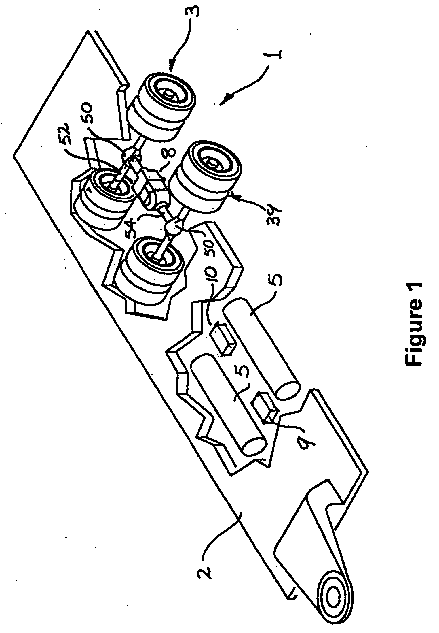
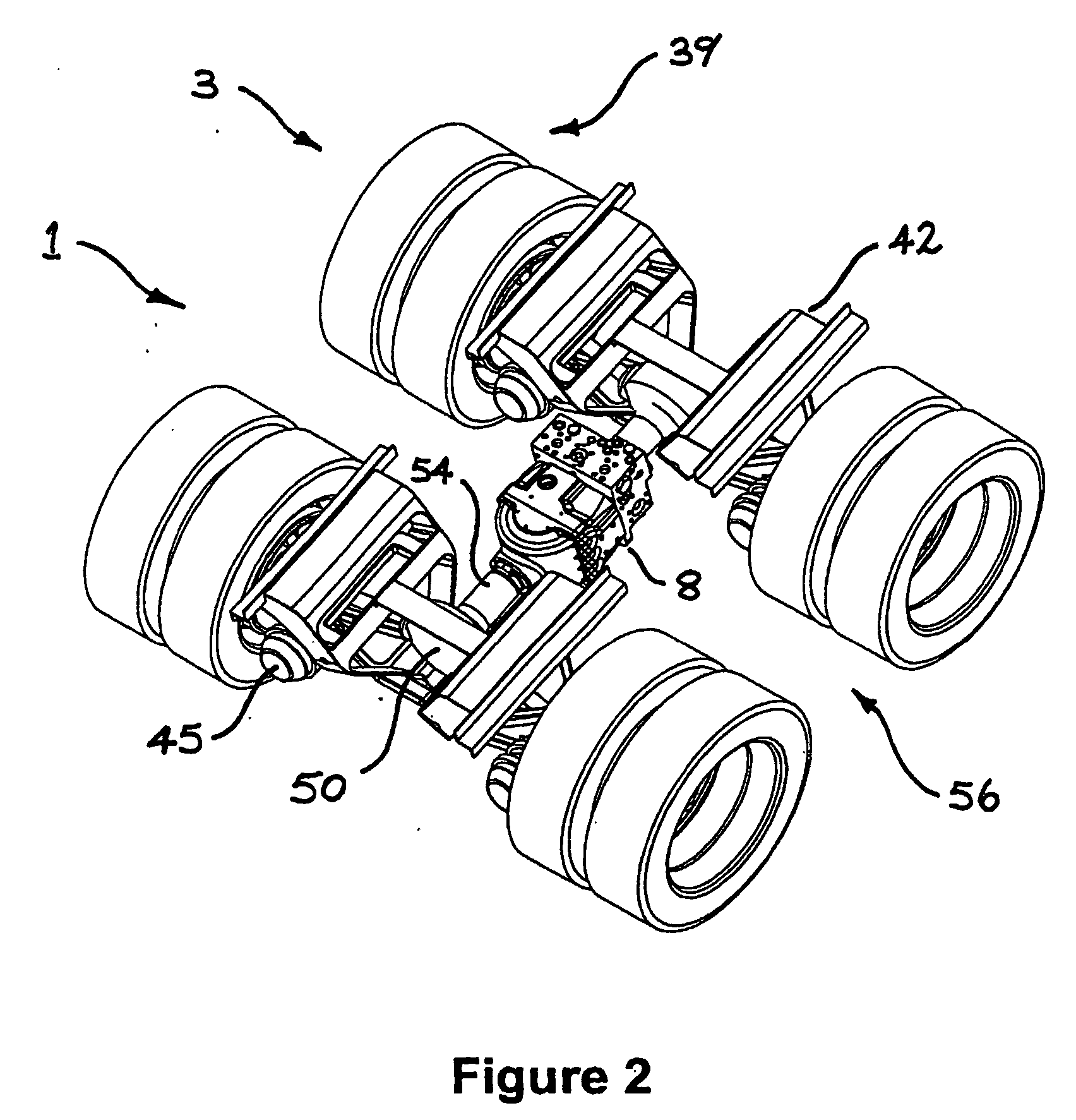
[0045] Referring to the drawings, the invention provides a regenerative drive and energy management system (RDS) 1, adapted for use with a compound vehicle including a primary source of motive power, or prime mover (not shown). The prime mover would typically include an engine connected to driven wheels via a transmission and primary drive train (also not shown), and coupling means adapted for connection to a trailer 2. The trailer 2 includes wheels 3 isolated from the primary drive train.

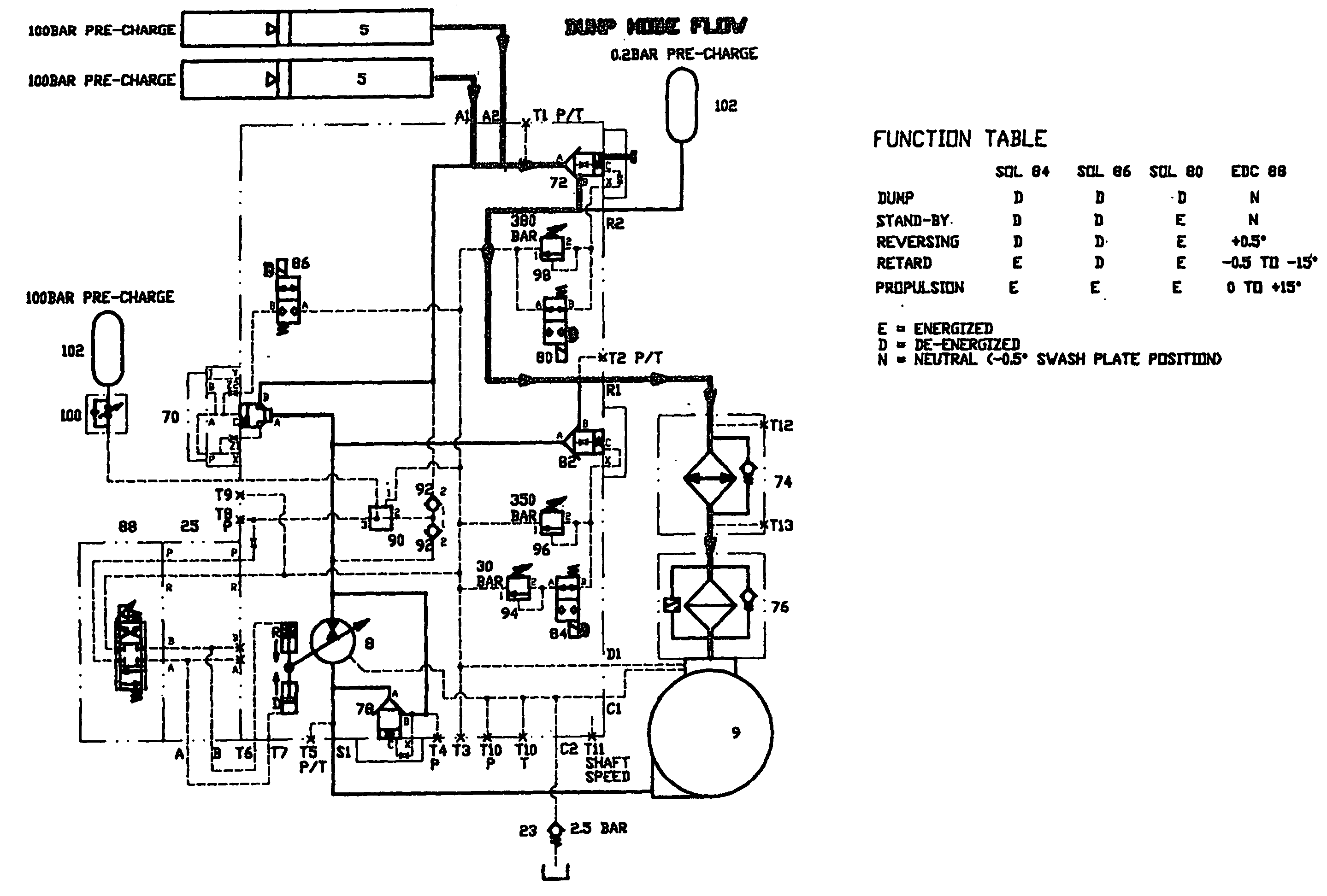
[0046] In broad overview, the RDS includes energy accumulation means in the form of a series of accumulators 5, each operable selectively to store and release energy through controlled receipt and release of pressurised hydraulic fluid, as described in more detail below. The system further includes a positive displacement hydraulic pump / motor assembly 8 in fluid communication with the accumulators, a low-pressure hydraulic reservoir 9 in fluid communication with the pump / motor assembly, and a cont...


PUM


Abstract

A regenerative energy management system (1) adapted for use with a compound vehicle including a prime mover, drive train and a trailer (2) including independent wheels (3) isolated from the prime mover drive train. The system (1) includes energy accumulation means (5) operable selectively to store and release energy through controlled receipt and release of pressurised hydraulic fluid; a positive displacement hydraulic pump / motor assembly (8) in fluid communication with the energy accumulation means (5); and a low-pressure hydraulic reservoir (9) in fluid communication with pump / motor assembly. The pump / motor assembly (8) has a drive shaft for connection to at least one of the wheels (3). In a braking mode, the assembly (8) retards the associated wheel (3) by pumping hydraulic fluid into the accumulation means (5) while in a driving mode, it supplies supplementary power using hydraulic fluid from the accumulation means (5) and in a neutral mode, it exerts no substantial driving or retarding influence on the wheel (3).

Description

FIELD OF INVENTION [0001] The present invention relates generally to land haulage vehicles, and in particular to haulage vehicles having at least one wagon or trailer connected to a prime mover. [0002] The invention has been developed primarily for use with road transport vehicles and will be described predominantly hereinafter in the context of semi-trailers of the type typically drawn behind prime movers. It should be appreciated, however, that the invention is not limited to this particular field of use, being readily adaptable to any type of wagon or trailer, whether pushed or pulled, in virtually any application. Other applications include rail carriages, bogies and wagons, articulated lorries, articulated buses, road trains comprising multiple trailers, caravans and boat trailers. It should also be appreciated that the invention is applicable to off-road applications. BACKGROUND OF THE INVENTION [0003] The following discussion of the prior art is intended solely to place the i...

Claims


Application Information

Patent Timeline
Patent Type & Authority Applications(United States)
IPC IPC(8): F16D31/02B60K6/12B60K17/10B60T1/093B60T1/10B60T8/00B60T8/17B60T10/04B60T13/58B60T13/74F16H61/42F16H61/439
CPCB60G2200/144B60L2200/26B60G2204/143B60G2300/04B60K6/12B60L2240/441B60L2240/486B60T1/10B60T8/00B60T8/1708B60T10/04B60T13/586B60T13/74B60T2270/606B60W2300/145B60W2510/0638B60W2510/0671B60W2540/16B60Y2200/14F16H61/439Y02T10/6208Y02T90/16F16H61/4165B60Y2400/435B60G2200/422Y02T10/62
Inventor RUSH, ALLAN
Owner PERMO DRIVE RES & DEV
Why Eureka
Try Eureka