Hydraulic downhole oil recovery system

Inactive Publication Date: 2006-01-05
CRAWFORD JOE
View PDF15 Cites 20 Cited by
  • Summary
  • Abstract
  • Description
  • Claims
  • Application Information

AI Technical Summary

Benefits of technology

[0044] As mentioned, Applicant's invention circulates a water-based fluid, rather than hydraulic fluid, throughout the system. This substitution promotes both the novel design and great efficiency of the present invention. More specifically, the use of water-based fluid provides for a much greater operating efficiency. That is, typical hydraulic fluid is compressible and therefore requires significantly more pump strokes to “pressure up” than a column of water-based fluid. As a result, the efficiency of hydraulic fluid decreases over any appreciable distance as its compression causes wasted pump strokes, which directly translates to lost power. Because the present system uses incompressible water-based fluid, problems associated with fluid compressibility have been eliminated. Specifically, power loss is avoided as there is no appreciable loss in efficiency due to the compression of the circulated production fluid.
[0045] Other useful embodiments of the invention are thought to utilized additives that my increase the viscosity of the water-based hydraulic fluid. Such may involve the use of “oils” to form emulsions. These embodiments are thought to be particularly useful in further reducing fluid friction and fu

Problems solved by technology

Conventional oil recovery systems are hampered by limitations on both the depth and volume of oil that can be recovered.
Conventional oil recovery systems are relatively short-lived and require a high level of maintenance in view of the present device.
Current systems rely on large, cumbersome parts that are prone to leaking and causing wear and tear of standard production tubing.
A large portion of the problems associated with known oil recovery systems come from the secured-production tubing configuration of those systems.
Specifically, reciprocation of the sucker rod within the production tube causes wear and tear of the tubing.
As a result, leaks often originate within the tubing at the secured reciprocation location.
This leads to both inefficiency and environmental contamination.
Common oil recovery systems also present significant problems at the surface.
Surface pumps are loud, cumbersome, visually offensive, dangerous, and environmentally unfriendly.
As such, restrictions are placed on both where and when these systems can be used.
Prohibitive zoning restrictions are often based on the way the pumps look, how they sound, and the inconvenience they cause to people in th

Method used


Image

  • Hydraulic downhole oil recovery system
  • Hydraulic downhole oil recovery system

Examples


Embodiment Construction

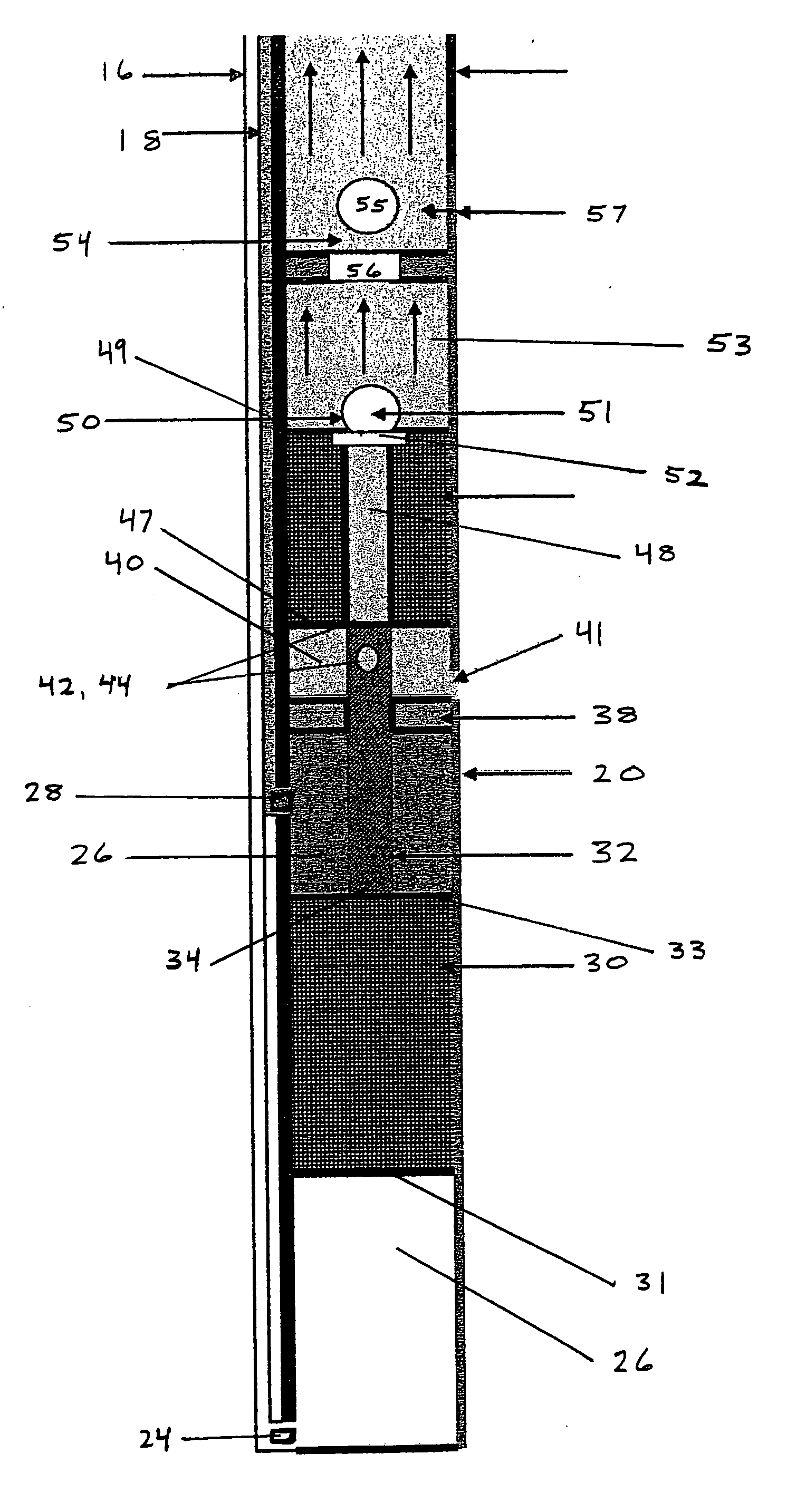
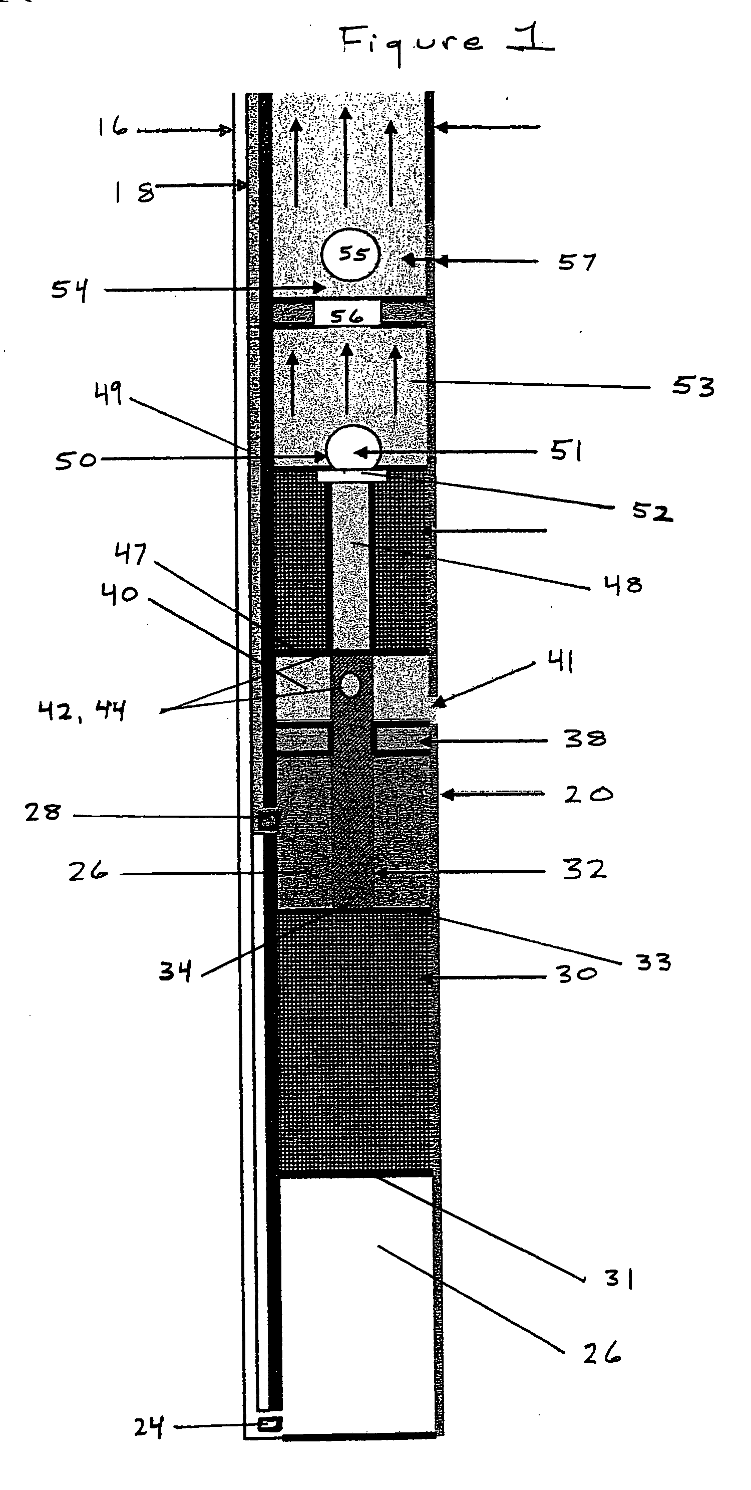
[0050] With reference to FIG. 1, the improved hydraulic down-hole oil recovery system of the present invention is identified generally by the reference number 10. In the preferred embodiment, device 10 is primarily made of alloy metal and coil tubing.

[0051] Referring principally to FIG. 1, device 10 includes surface pump unit 12. Surface pump unit 12 sends a production fluid 14 through upstroke powerline 16 during one cycle and sends production fluid 14 through downstroke powerline 18 in a following downstroke cycle. Surface unit 12 reversibly engages with power lines 16 and 18 so as to form a fluid-tight seal, such seal is formed by standard tube fittings as known in the art. In the preferred embodiment, pump unit 12 is pressure pump, modified to contain a “switch off pressure sensor”13 which reads the pressure at the surface pump on both the upstroke and the downstroke. At the point each stroke is carried out, pressure increases beyond a preset “switch off” point where sensor 13 ...


PUM


Abstract

An improved hydraulic downhole oil recovery system that incorporates an above ground unit and a submersible, reciprocating downhole pump unit. Water-based fluid, rather than hydraulic fluid, is responsible for actuating the reciprocating downhole pump unit. The water-based fluid is transferred through the system using coil, coil tubing. The system further relies upon coil exterior production tubing to provide exceptional advantage in deviated oil wells.

Description

CITATION TO PARENT APPLICATION(S) [0001] This is a continuation-in-part with respect to U.S. patent application Ser. No. 10 / 884,376, filed on Jul. 2, 2204, from which priority is claimed pursuant to 35 U.S.C. 120.BACKGROUND OF THE INVENTION [0002] 1. Field of The Invention [0003] Applicant's invention generally relates to an improved hydraulic downhole oil recovery system. More specifically, Applicant's invention relates to an oil recovery system that employs coil tubing, in both its production tubing and fluid transfer tubing, and water-based fluid, rather than hydraulic fluid, to offer its user tremendous advantages in view of systems known in the art. [0004] 2. Background Information [0005] Conventional oil recovery systems are hampered by limitations on both the depth and volume of oil that can be recovered. The present invention does away with these presently accepted limitations. In fact, known oil recovery systems can generally recover 400 barrels of oil per day, at a depth o...

Claims


Application Information

Patent Timeline
IPC IPC(8): E21B43/00E21B33/12
CPCE21B43/129
Inventor CRAWFORD, JOE
Owner CRAWFORD JOE
Why Eureka
Try Eureka