Diffractive optical element changer for versatile use in laser manufacturing

a technology of optical elements and array apparatuses, which is applied in metal-working apparatus, welding apparatus, manufacturing tools, etc., can solve the problems of inefficiency, time-consuming and inefficient laser processing systems, and application that does not address the process of changing the doe for additional ablation, etc., and achieves time-consuming and inefficient change of the doe using current conventional methods, even robotically, and cost. high

Inactive Publication Date: 2006-01-05
PANASONIC CORP
View PDF8 Cites 10 Cited by
  • Summary
  • Abstract
  • Description
  • Claims
  • Application Information

AI Technical Summary

Benefits of technology

[0010] In accordance with the present invention, a DOE array apparatus includes a plurality of different interchangeable DOEs for use with lasers in manufacturing for versatile tasks such as drilling holes or vias of various sizes and shapes and multiple ablation or material transformation patterns on the surface or inside an object. A method of using the apparatus in laser processing systems includes: determining a specification for the number of patterns ...

Problems solved by technology

However, laser processing systems are very costly and can be inefficient.
However, the '291 patent application does not address the process of changing the DOE for additional ablation patterns, (e.g., for patterning multi-leveled circuit boards).
Changing the DOE using current conventional methods, even robotically, can be time-consuming and inefficient and therefore costly.
However, this alternative would be more costly.
Also, in con...

Method used


Image

  • Diffractive optical element changer for versatile use in laser manufacturing
  • Diffractive optical element changer for versatile use in laser manufacturing
  • Diffractive optical element changer for versatile use in laser manufacturing

Examples


Embodiment Construction

[0022] The following description of the preferred embodiment(s) is merely exemplary in nature and is in no way intended to limit the invention, its application, or uses.

[0023] The present invention relates to a diffractive optical element (DOE) array apparatus and method of using the apparatus in laser processing systems. More specifically, the present invention relates to a way of interchanging DOEs for use with lasers in manufacturing for versatile tasks such as drilling holes or vias of various sizes and shapes and multiple ablation or material transformation patterns in a surface of an object.

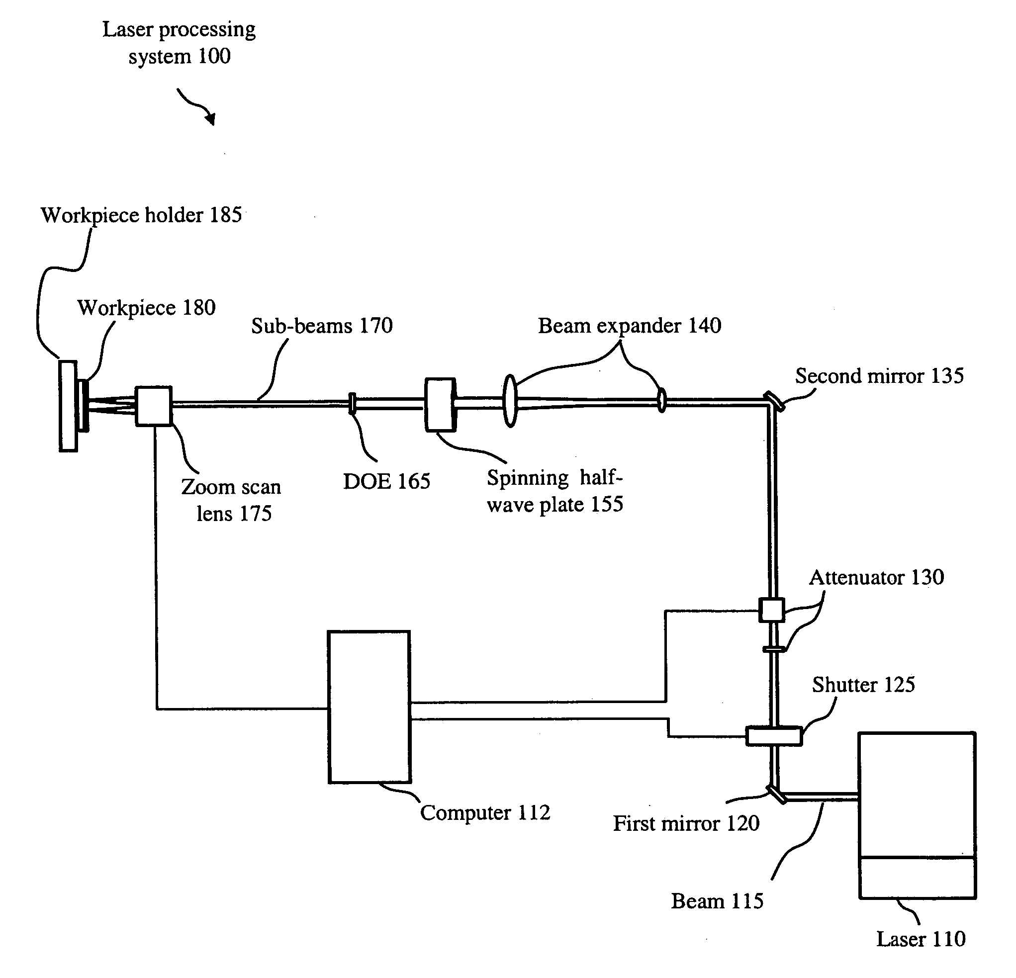
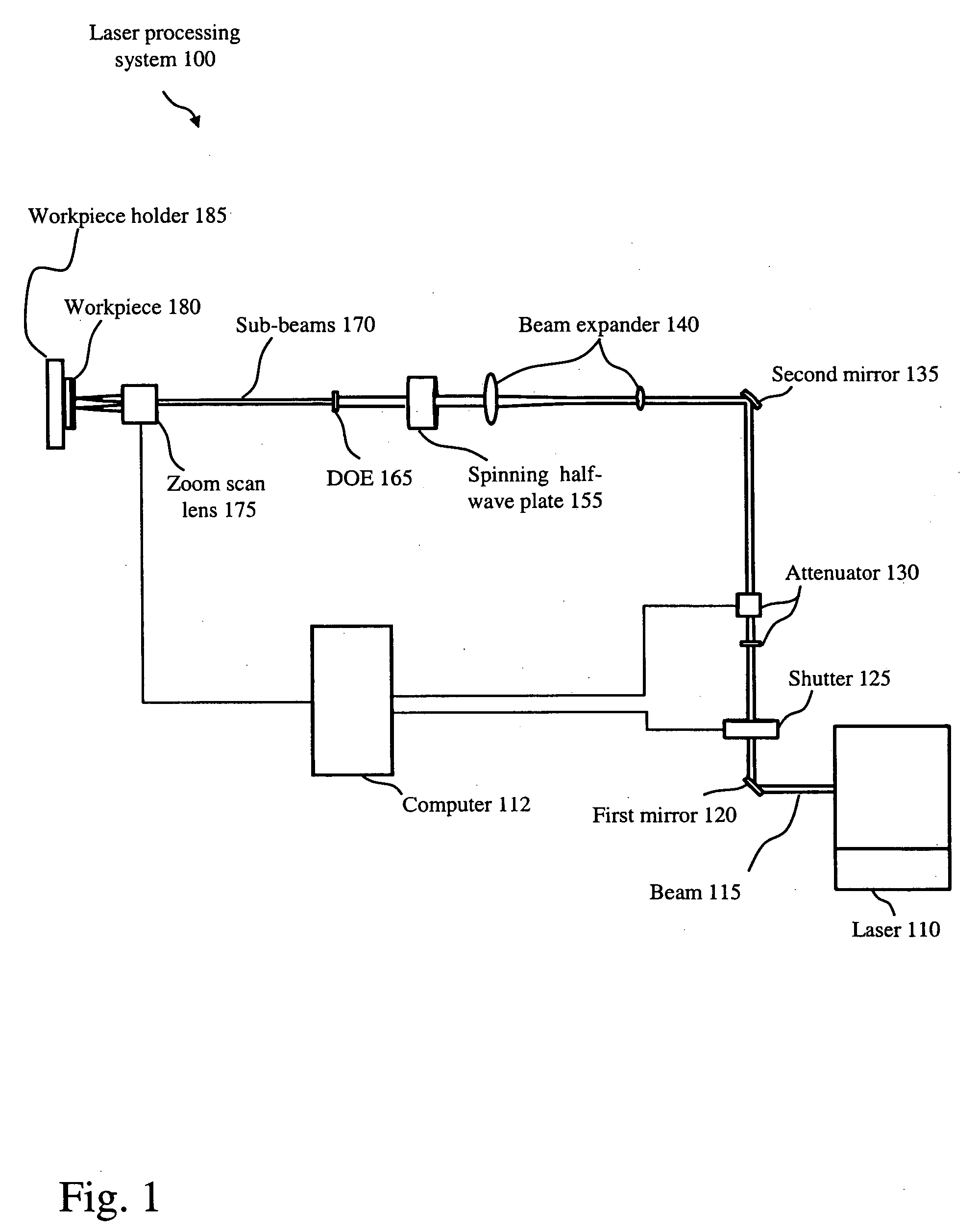
[0024]FIG. 1 illustrates a subassembly 100 of a laser processing system for drilling holes or vias of various sizes and shapes and multiple ablation or material transformation patterns in a surface of an object including a beam 110, a plurality of DOEs 130a, 130b, 130c, 130d, 130e, 130f, 130g, 130h and 130i (note that subassembly 100 may contain any number of DOEs and is not limited to ni...


PUM

PropertyMeasurementUnit
Sizeaaaaaaaaaa
Dimensionaaaaaaaaaa

Abstract

A DOE array apparatus includes a plurality of different interchangeable DOEs for use with lasers in manufacturing for versatile tasks such as drilling holes or vias of various sizes and shapes and multiple ablation or material transformation patterns in a surface of an object. A method of using the apparatus in laser processing systems includes: determining a specification for the number of patterns and/or the number of layers to be patterned, designing the appropriate number of DOEs according to the product specification, assembling the DOEs into an array to be used in a laser processing system, ablating the layer on the object through laser processing, determining whether more patterns on the layer are to be processed, determining whether more layers are to be patterned, and changing and aligning the DOE for the next laser ablation or material transformation pattern to be processed.

Description

FIELD OF THE INVENTION [0001] The present invention relates to a diffractive optical element (DOE) array apparatus and method of using the apparatus in laser processing. More specifically, the present invention relates to a way of interchanging DOEs for use with lasers in manufacturing for versatile tasks such as drilling holes or vias of various sizes and shapes and multiple ablation or material transformation patterns in a surface of an object BACKGROUND OF THE INVENTION [0002] There is an ever-increasing demand for smaller and smaller electronic devices in today's high-tech marketplace. As a result, new and innovative fabrication techniques have become a focal point of many manufacturers. Many manufacturers have turned to laser processing as a means of fabrication, (e.g. for blowing fuses, via and hole drilling, ablation patterning, resistor trimming, material transformation such as curing monomers to polymers, changing refractive index, transmissivity or reflectivity and etc.). ...

Claims


Application Information

Patent Timeline
IPC IPC(8): B23K26/38B23K26/067
CPCB23K26/0608B23K26/383B23K26/067B23K26/384
Inventor HOGAN, DANIELLIU, XINBING
Owner PANASONIC CORP
Why Eureka
Try Eureka