
Rotation angle detecting device

a detection device and rotation angle technology, applied in the direction of mechanical conversion of sensor output, optical radiation measurement, instruments, etc., can solve the problems of reducing manufacturing yield, difficult to obtain output voltage value, and high cost so as to achieve the effect of easy assembly of rotation angle detection devices

Active Publication Date: 2006-01-05
ALPS ALPINE CO LTD
View PDF2 Cites 23 Cited by
  • Summary
  • Abstract
  • Description
  • Claims
  • Application Information

AI Technical Summary

Benefits of technology

[0014] The invention has been finalized in view of the drawbacks inherent in the conventional rotation angle detecting device. An object of the invention is that it provides a rotation angle detecting device which is capable of adjusting an output voltage value of an absolute-type rotation detecting device during assembling and which has a lower manufacturing cost.
[0016] If the slider rotating plate is rotated in the circumferential direction, the relative position of the slider with respect to the resistance board changes, and an output voltage value of an analog absolute-type rotation detecting unit which is constituted by the resistance board and the slider changes. Therefore, after the circular pin insertion holes formed in the case and the cover are disposed so as to face the circular pin insertion hole formed in the code wheel, the output voltage value of the absolute-type rotation detecting unit, which is measured before the case and the cover are incorporated into each other, can be deviated from a predetermined value according to an absolute angle of 0°. In this case, by rotating the slider rotating plate in the longitudinal range of the pin insertion hole having a circular-arc shape, the output voltage value of the absolute-type rotation detecting unit coincides with a predetermined value, and then the case and the cover are incorporated with each other by snap-connection. After that, the fixing pin passes through the respective circular pin insertion holes and the arc-shaped pin insertion hole, so that the rotation angle detecting device can be fixed in a shipping state. Therefore, a rotation angle detecting device having a good quality can be easily manufactured with a high yield.
[0018] As such, if an incremental-type rotation detecting unit is constituted by the code wheel having the slit string formed therein and the photo-interrupter, signal detection can be performed in a non-contact state. In addition, there is no case where signal detection precision is degraded due to the degradation of reflectance caused by dust adhered to the code wheel, unlike a case in which a code pattern string is formed on a reflecting plate. Therefore, signal detection can be performed precisely and reliably.
[0020] As such, if the connection pin through which the resistance board and the circuit board are electrically connected to each other is provided on the resistance board, the connection between the resistance board and the circuit board can be completed only by plugging the leading end of the connection pin into the circuit board when the rotation angle detecting device is assembled. Therefore, the rotation angle detection device can be assembled easily.

Problems solved by technology

However, the output voltage value of the analog absolute-type rotation detecting device is determined by the contact position of the slider with respect to the resistance pattern when the fixing pin passes through the respective pin insertion holes formed in the housing and the rotating section, and the voltage value is varied by a forming error of the resistance pattern and an assembling error of the resistance board into the housing.
Therefore, it is hard to obtain an output voltage value in the above-described strict range, even though forming precision of the resistance pattern and assembling precision of the resistance board into the housing are designed to be enhanced.
Therefore, the manufacturing yield is lowered, and a rotation angle detecting device becomes expensive.
However, the number of components increases, and an assembling operation becomes complicated, which makes it difficult to obtain an effect of a reduction in cost.

Method used


Image

  • Rotation angle detecting device
  • Rotation angle detecting device
  • Rotation angle detecting device

Examples


Embodiment Construction

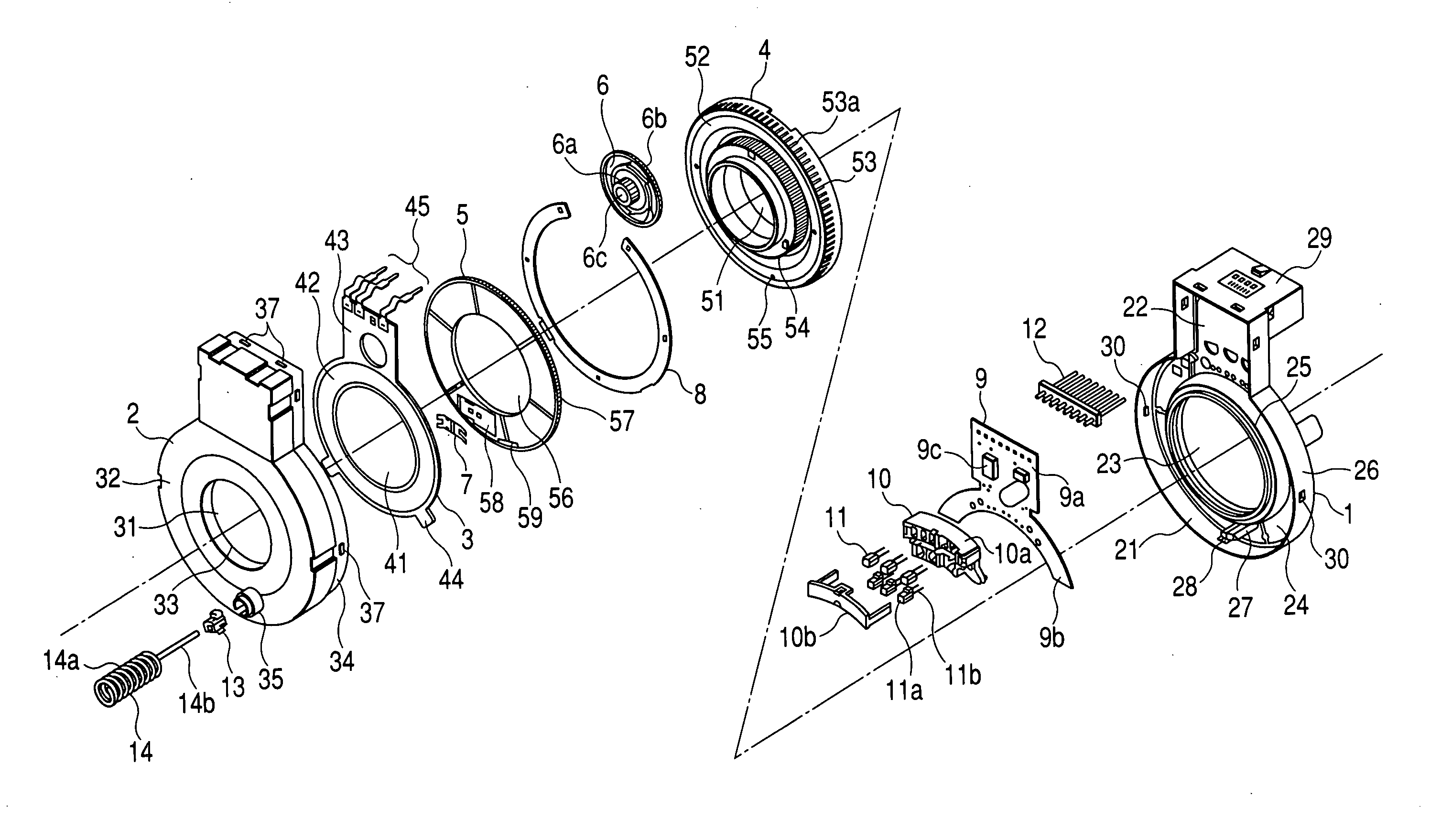
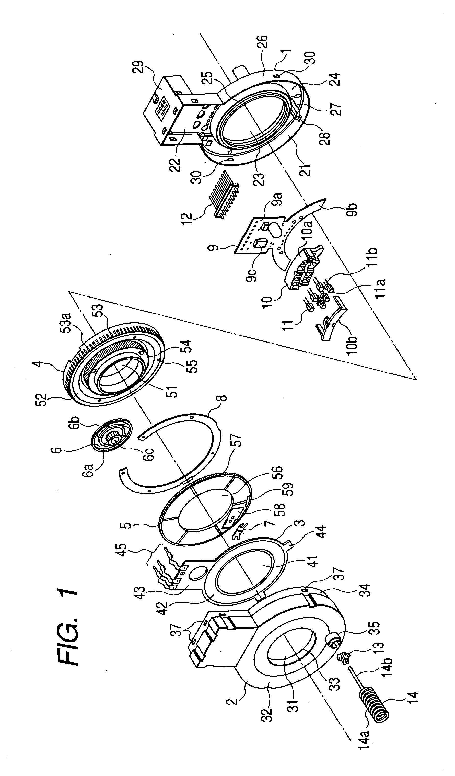
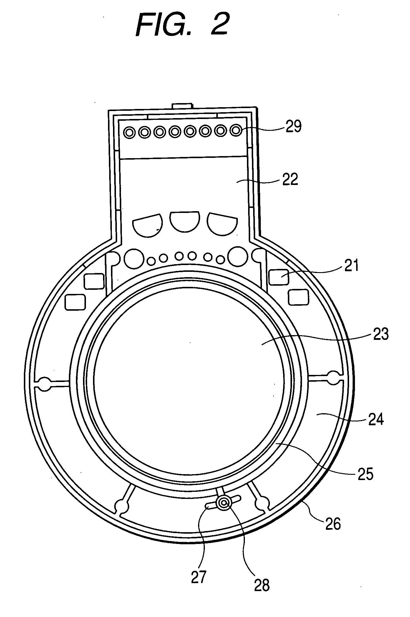
[0024] Hereinafter, a rotation angle detecting device according to an embodiment of the invention will be described with reference to FIGS. 1 to 3. FIG. 1 is an exploded perspective view of a rotation angle detecting device according to an embodiment of the invention. FIG. 2 is a plan view of a case according to an embodiment of the invention, as viewed from an inner surface thereof, and FIG. 3 is a plan view of a cover according to an embodiment of the invention, as viewed from an outer surface thereof.

[0025] As shown in FIG. 1, the rotation angle detecting device according to the present embodiment mainly includes a case 1, a cover 2, a resistance board 3 which is fixed on the inner surface of the cover 2, a code wheel 4 and a slider rotating plate 5 which are rotatably provided inside a housing constituted by a combination of the case 1 and the cover 2, a gear 6 decelerating the rotation of the code wheel 4 to transmit the reduced rotating force to the slider rotating plate 5, a...


PUM


Abstract

A rotation angle detecting device includes a housing which is constituted by a combination of a case and a cover; a resistance board; a code wheel; a slider rotating plate; a slider; a circuit board; signal detecting elements; and a gear which transmits the rotation of the code wheel at a predetermined speed reduction ratio to the slider rotating plate, which are enclosed in the housing. Circular pin insertion holes are formed in positions where the code wheel, the case, and the cover face each other, respectively. A pin insertion hole having a circular-arc shape is formed in the slider rotating plate.

Description

BACKGROUND OF THE INVENTION [0001] 1. Field of the Invention [0002] The present invention relates to a rotation angle detecting device which is applied to a rudder angle sensor for a car, and more specifically to an adjusting unit for a neutral position (a position where an absolute angle is 0°) in a rotation angle detecting device including a digital incremental-type rotation detecting unit which detects a rotation angle within 360° to output a digital code signal and an analog absolute-type rotation detecting unit which detects the number of rotations more than one rotation to output an analog signal. [0003] 2. Description of the Related Art [0004] Conventionally, a technique is known in which a rotation angle detecting device is provided between a steering shaft and a chassis of a car so that the damping force of a suspension, the shift position of an automatic transmission, and steering of a rear wheel in a four-wheel steering car are controlled based on the steering angle, stee...

Claims


Application Information

Patent Timeline
IPC IPC(8): G01D5/34
CPCG01D5/04G01D11/245G01D5/165
Inventor SANO, TADASHI
Owner ALPS ALPINE CO LTD
Learn More