Air bubble removal in an ink jet printer

a technology of air bubbles and ink jet printers, which is applied in the field can solve the problems of increasing the size reducing the recording quality of the head, and reducing the efficiency of ink jet printers, so as to achieve the effect of efficient removal of air bubbles collected and small siz

Active Publication Date: 2006-01-05
BROTHER KOGYO KK
View PDF10 Cites 35 Cited by
  • Summary
  • Abstract
  • Description
  • Claims
  • Application Information

AI Technical Summary

Benefits of technology

[0011] It is another object of the present invention to provide such an ink jet printer which can efficiently remove air bubbles collected in an air buffer chamber or an air-bubble collecting chamber which is provided, together with a recording head, on a carriage.
[0012] It is another object of the present invention to provide such an ink jet printer which can be produced in a small size.

Problems solved by technology

However, in the ink jet printer, if air bubbles (or air) are contained in the ink present in the recording head, the recording head may fail to eject the ink, or the recording quality of the head may lower.
In the tube-supply-type ink jet printer, air cannot be prevented from permeating the tube and dissolving in the ink, because of the natural property of the material used to form the tube.
However, in the above-indicated ink jet printer, since the ink tank communicates with the atmosphere, air (or air bubbles) is likely to mix with the ink being circulated.
Thus, the ink jet printer is complicated and is increased in size.

Method used


Image

  • Air bubble removal in an ink jet printer
  • Air bubble removal in an ink jet printer
  • Air bubble removal in an ink jet printer

Examples


first embodiment

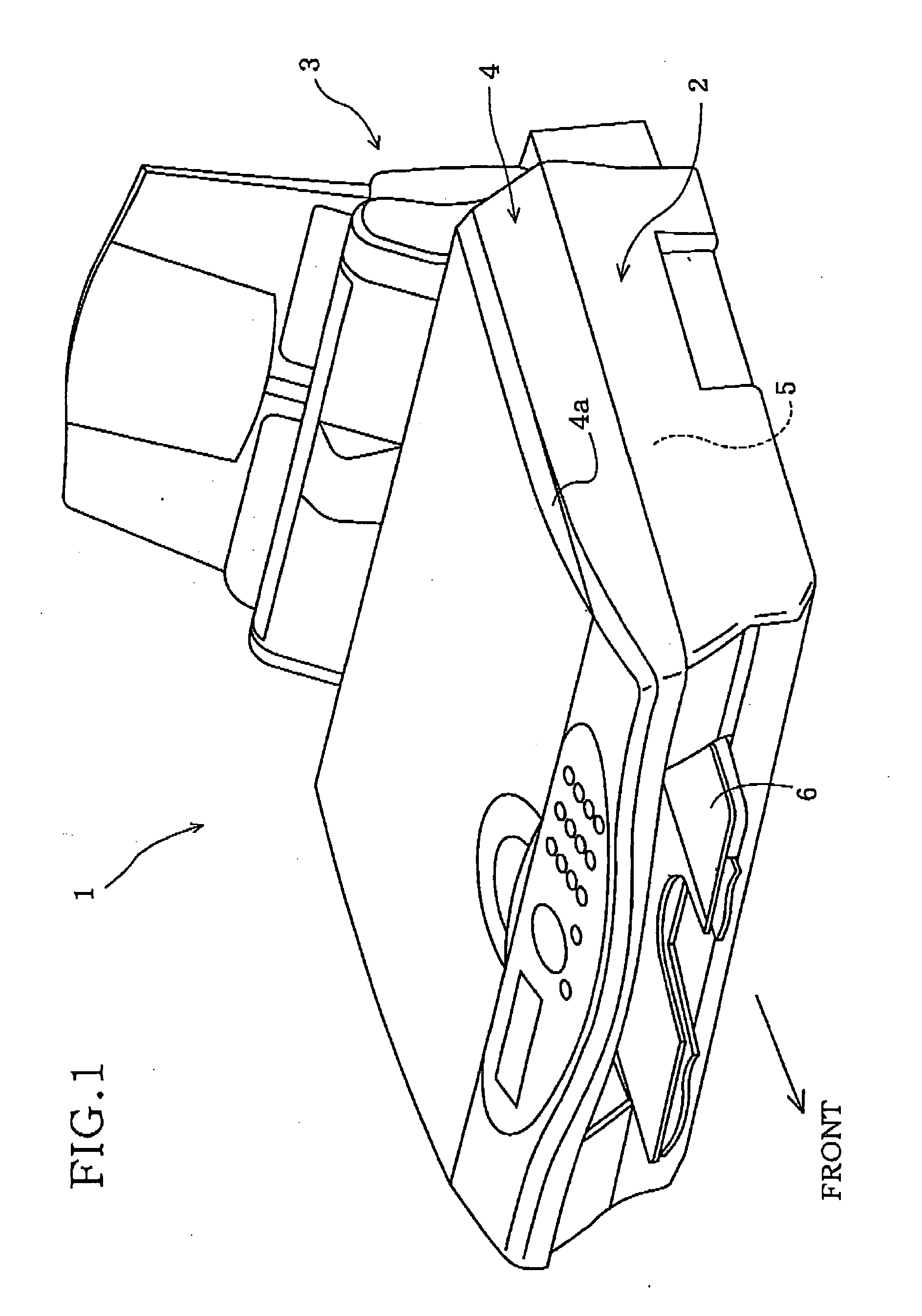
[0110] Hereinafter, there will be described a preferred embodiment of the present invention by reference to the drawings. the present invention relates to a multifunctional apparatus % WC) 1 having a printer function, a copier function, a scanner function, and a facsimile function. As shown in FIG. 1, the MFC 1 includes a housing 2; a sheet supplying device 3 provided in a rear end portion of the housing 2; and an original reading devise 4, for the copier and facsimile functions, that is provided in an upper portion of the housing 2, and in front of the sheet supplying device 3. An ink jet printer 5 (described later) for the printer function entirely occupies a lower portion of the housing 2, below the original reading device 4; and a sheet collecting tray 6 is provided in front of the ink jet printer 5, so as to collect a recording medium, e.g., a sheet of paper, P, on which recording or printing has been performed by the printer 5.

[0111] The original reading device 4 is constructe...

second embodiment

[0213] Next, the recording head unit 203 mounted on the carriage 209 will be described by reference to FIGS. 28 and 29. In the second embodiment, the full color image recording head unit 203 includes a head holder 220, an ink-jet recording head 221, the buffer tank 213, and an air discharging valve device 226. The head holder 220 has a box-like configuration. The recording head 221 is fired to a lower surface of a bottom wall 220a of the head holder 220; and the buffer tank 213 is fixed to an upper surface of the bottom wall 220a.

[0214]FIG. 28 is a bottom view of the recording head 221. As shown in this figure, a lower surface of the recording head 221 supports four arrays of nozzles 222a, 222b, 222c, 222d corresponding to the black ink 0310, the cyan ink (C), the magenta ink (M), and the yellow ink (Y), respectively, in the order of description, in the direction from the left-hand side to the right-hand side, such that each of the four arrays of nozzles 222a to 222d extends in a d...

third embodiment

[0262] In the third embodiment, four color inks, i.e., black, cyan, magenta, and yellow inks are supplied to two recording heads 221 which have ten arrays of nozzles 222 (222a, 222b, 222c, 222d, 222e, 222f, 222g, 222h, 222i, 222j), in total each array of which ejects a corresponding one of the four color inks. The two recording heads 221 are arranged in a recording direction in which the recording heads 221 are moved, and the two heads 221 are fixed to a head holder 220.

[0263] In the third embodiment, a buffer tank 313 supplies, to each of the two recording heads 221, corresponding three color inks. More specifically described, although four ink flow inlets 247 (247a, 247b, 247c, 247d) are provided for the four color ins, respectively, that is, one inlet 247 is provided for each color in, as shown in FIG. 38, two flow outlets 241 (241a, 241b, 241c, 241d) are provided for each color ink. Since the third embodiment is a modified form of the second embodiment, the same reference numera...


PUM


Abstract

An ink jet printer including a carriage which is movable relative to a sheet of paper, a recording head which is mounted on the carriage and records an image on the sheet by ejecting a droplet of ink toward the sheet, one or more ink tanks which store the ink or inks to be supplied to the recording head, a buffer tank which is mounted on the carriage, and one or more ink flow passages in which the inks are supplied from the ink tanks to the recording head via the buffer tank. The buffer tank has, at a height position higher than a height position where the recording head is provided, one or more air buffer chambers which accommodate respective amounts of the inks, and collect air bubbles produced in the ink flow passages. The printer further includes one or more air bubble discharging passages which communicate, at one ends thereof, with upper portions of the air buffer chambers, and discharge, via the other ends thereof, the air bubbles collected by the air buffer chambers.

Description

[0001] This is a Continuation-in-Part of International Application No. PCT / JP2004 / 001084 filed Feb. 3, 2004, which claims the benefits of Japanese Patent Application No. 2003-027649 filed Feb. 4, 2003, Japanese Patent Application No. 2003-308308 filed Sep. 1, 2003, Japanese Patent Application No. 2008-308475 filed Sep. 1, 2003, and Japanese Patent Application No. 2003-385796 filed Nov. 14, 2003.BACKGROUND OF THE INVENTION [0002] 1. Field of the Invention [0003] The present invention relates to an ink jet printer and particularly to such an ink jet printer which can not only collect air bubbles generated in one or more ink flow passages, so as to maintain its high recording quality, and but also efficiently remove the collected air bubbles. [0004] 2. Discussion of Related Art [0005] There has conventionally been known a tube-supply-type ink jet printer which supplies ink to a recording head mounted on a movable carriage, via a flexible tube, from an ink tank fired in a housing. An ex...

Claims


Application Information

Patent Timeline
Patent Type & Authority Applications(United States)
IPC IPC(8): B41J2/175B41J2/19
CPCB41J2/19B41J2/17513
Inventor UMEDA, TAKAICHIROKAGA, HIKARUSUZUKI, TSUYOSHISHIMIZU, SEIJIUSUI, TAKAMASASHIMIZU, YOICHIRO
Owner BROTHER KOGYO KK
Why Eureka
Try Eureka