Phase-change ink jet printing with electrostatic transfer

a technology of electrostatic transfer and ink jet printing, which is applied in the field of high-speed industrial ink jet printing, can solve the problems of ink jet printhead damage, ink jet orifice contamination, and high cost of electronic or offset printing equipment for such wide format output, and achieve the effect of accurate printing on the receiver

Inactive Publication Date: 2006-01-05
EASTMAN KODAK CO
View PDF22 Cites 40 Cited by
  • Summary
  • Abstract
  • Description
  • Claims
  • Application Information

AI Technical Summary

Benefits of technology

[0014] It is an object of this invention to provide a high-resolution ink jet printer and method of

Problems solved by technology

More specifically, ink jet printers appear especially attractive for wide format output (e.g., eighteen inches or wider), because electrographic or offset printing equipment for such wide format output is extremely costly.
In conventional ink jet printers, however, such close spacing often results in contamination to the ink jet orifices from dust carried by the receiver, or from fibers of the receiver itself.
The ink jet printhead may even become damaged by raised areas of the receiver itself, or by contaminants at the receiver surface, that actually touch the ink jets as the receiver passes by, especially in high-speed printers.
In the industrial printing context, the control of this precise printhead-to-receiver spacing over the desired wide-format receiver width is also very difficult.
The heating of the intermediate medium ca

Method used


Image

  • Phase-change ink jet printing with electrostatic transfer
  • Phase-change ink jet printing with electrostatic transfer
  • Phase-change ink jet printing with electrostatic transfer

Examples


Embodiment Construction

[0025] The present invention will be described in connection with its preferred embodiments, namely as implemented into an industrial size wide-format printing machine, because of the particular benefits provided by this invention in such an application. However, it is contemplated that this invention will also be beneficial in other applications of printing machines, and in connection with printing machines operating according to different mechanisms. Accordingly, it is to be understood that the following description is provided by way of example only, and is not intended to limit the true scope of this invention as claimed.

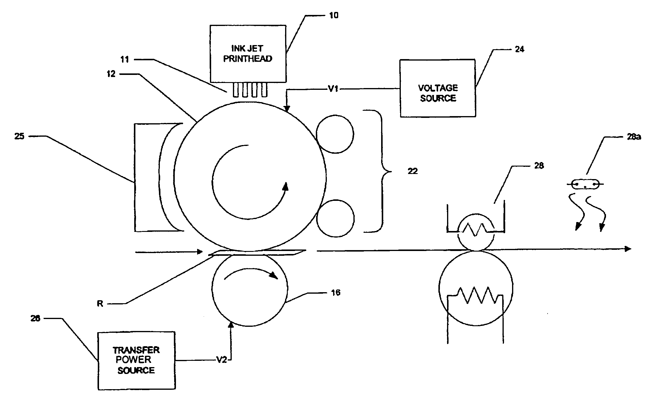
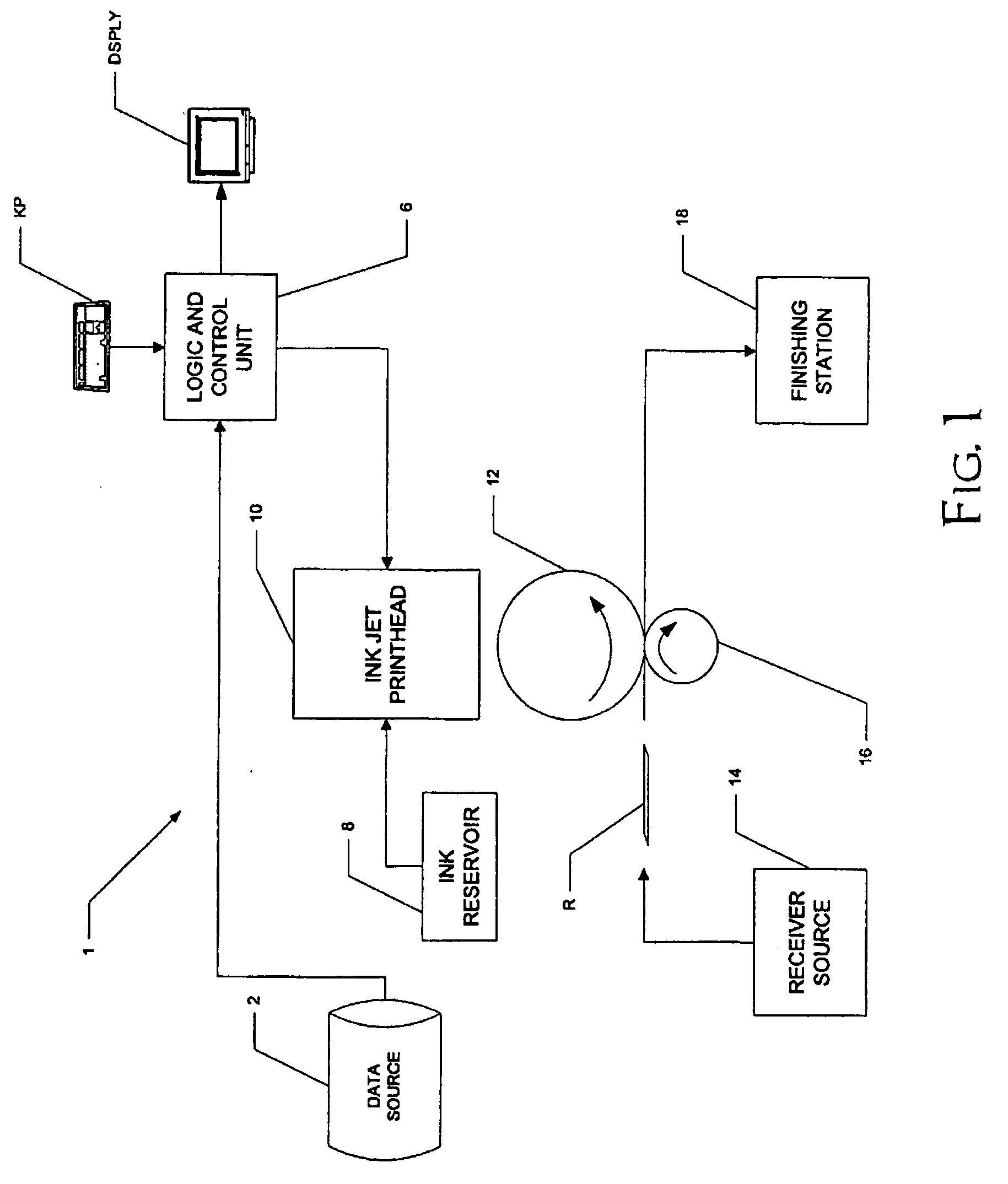
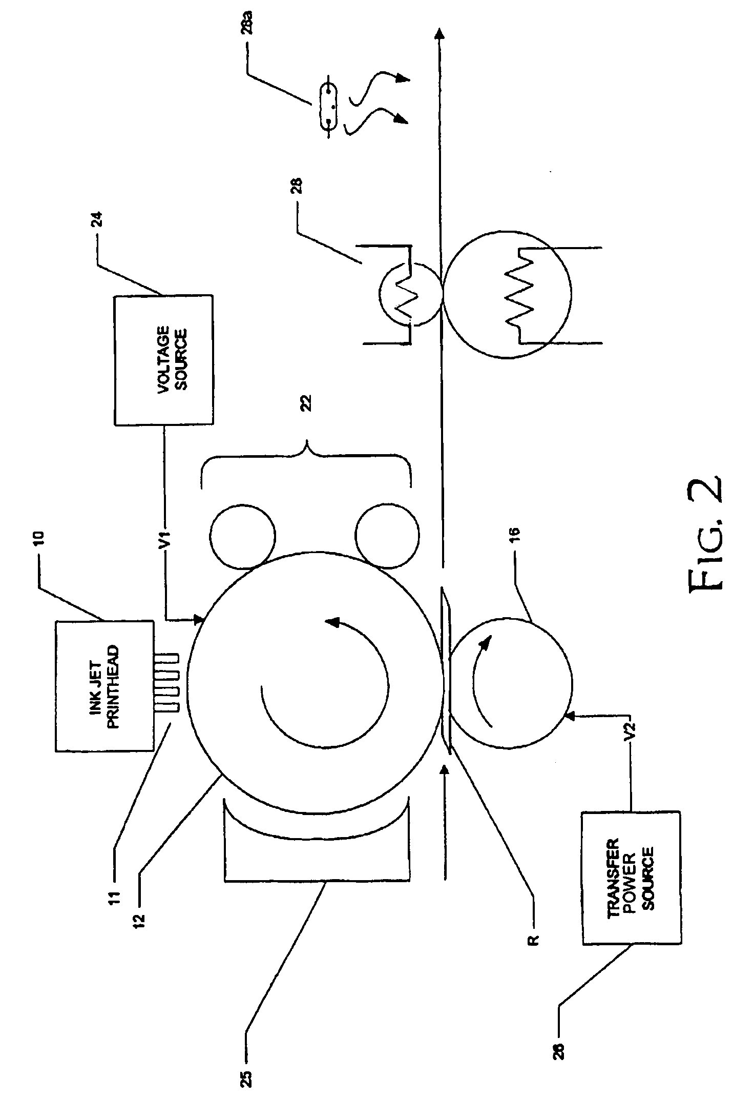
[0026]FIG. 1 is a block diagram illustrating, in a general sense, the construction of printing machine 1 according to the preferred embodiment of the invention. Data source 2 generically refers to a source of the image to be printed; examples of data source 2 include disk or solid state memory that stores and receives digital data corresponding to the printed i...


PUM


Abstract

A printing machine, comprising an intermediate medium; an ink jet printhead, for dispensing phase-change ink droplets at selected locations of a surface of the intermediate medium, the selected locations corresponding to an image to be printed; a receiver source, for providing a receiver; and a transfer station, for electrostatically transferring the dispensed phase-change ink droplets to the receiver.

Description

CROSS-REFERENCE TO RELATED APPLICATIONS [0001] Not applicable. STATEMENT REGARDING FEDERALLY SPONSORED RESEARCH OR DEVELOPMENT [0002] Not applicable. BACKGROUND OF THE INVENTION [0003] This invention is in the field of printing, and is more specifically directed to high-speed industrial ink jet printing. [0004] As a result of continuing technological advances in the field, ink jet printing has become more popular in recent years, over a wider range of printing applications. For example, color ink jet printers with very high resolution (on the order of 600 dpi), and thus capable of photographic quality output, are now available even at consumer prices. [0005] Ink jet printing is now also becoming popular in industrial applications. As mentioned above, ink jet printers provide excellent resolution at relatively low cost, and are especially attractive for the printing of small run jobs. Ink jet printers also can provide a great deal of flexibility in the printing of a wide range of for...

Claims


Application Information

Patent Timeline
IPC IPC(8): B41J2/01B41J2/175
CPCB41J2/17593B41J2/0057
Inventor STELTER, ERIC C.GUTH, JOSEPH E.
Owner EASTMAN KODAK CO
Why Eureka
Try Eureka