Eureka AIR delivers breakthrough ideas for toughest innovation challenges, trusted by R&D personnel around the world.

Geotechnical barrier

Active Publication Date: 2006-01-05
AQUATAN
View PDF8 Cites 8 Cited by
  • Summary
  • Abstract
  • Description
  • Claims
  • Application Information

AI Technical Summary

Benefits of technology

[0024] The method may include providing spacing means for spacing the first barrier layer from the second barrier layer. Then, the spacing means may comprise a drainage layer of at least one non-synthetic material. Instead, the spacing means may be of a geosynthetic material. The spacing means may comprise a cuspated membrane or geosynthetic drain of a plastics material. The cuspated membrane may comprise a plastics material sheet that has a multiplicity of projections extending for one side thereof. Further, the projections may be hollow and the majority of the hollow projections may be filled with a material to inhibit collapse of the projections under compressive forces.

Problems solved by technology

Laying the upper geomembrane or layer after the GCL has been hydrated may cause mechanical damage to the GCL.
For this reason, in many installations the GCL is not hydrated, resulting in a reduction in the reliability and performance of the GCL.
Difficulties with hydration of the GCL are magnified where the GCL is located on a slope.
In summary, in conventional geotechnical barriers using GCLs there is a problem of the hydration of the GCL.
In addition, decomposition of material in waste sites may generate high temperatures.
Such high temperatures may shorten the life of the membrane or reduce its geotechnical performance.

Method used


Image

  • Geotechnical barrier
  • Geotechnical barrier
  • Geotechnical barrier

Examples


Embodiment Construction

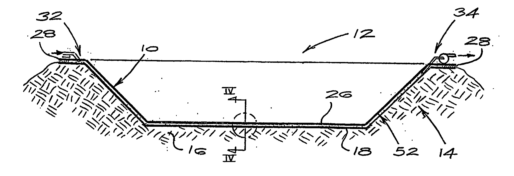
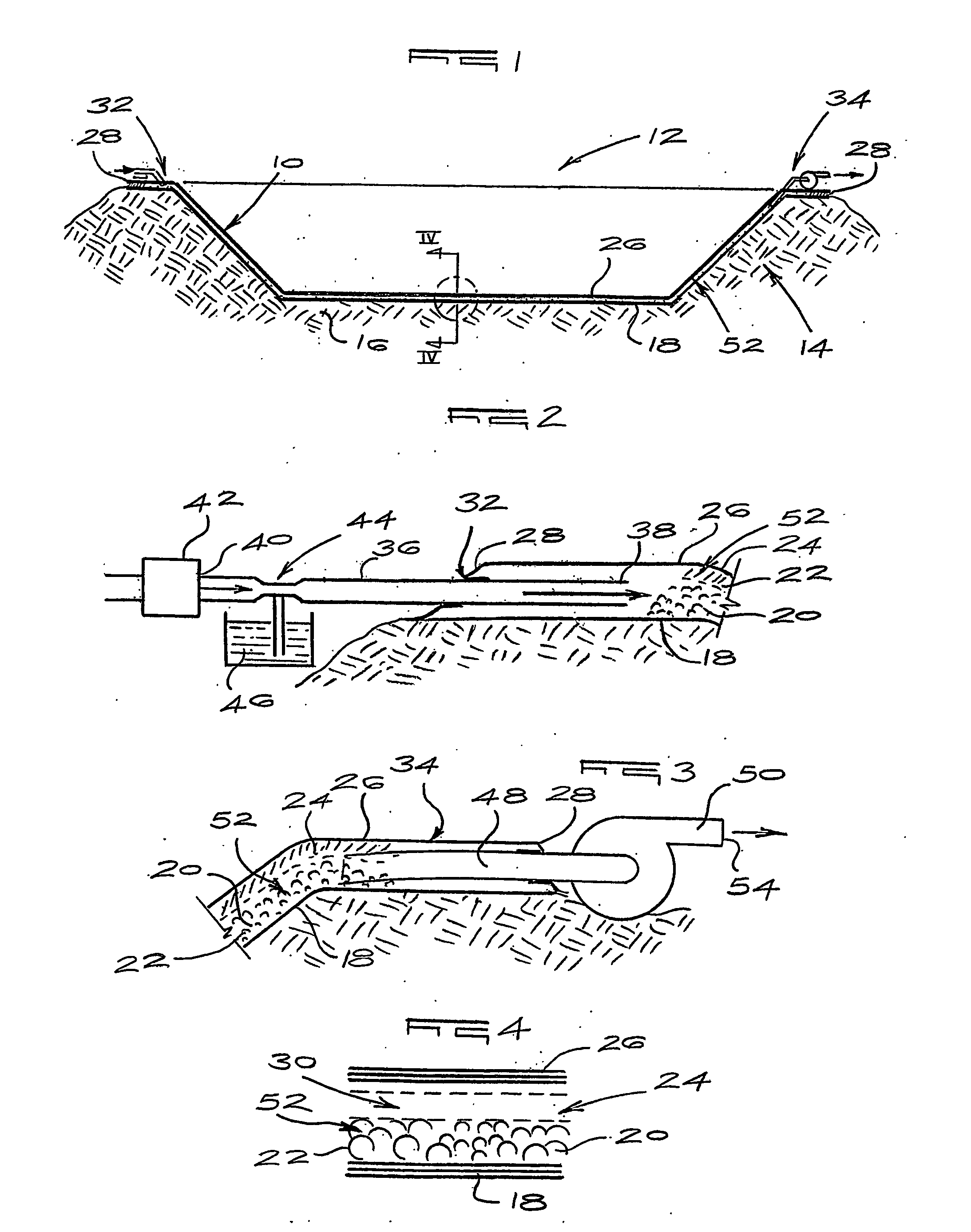
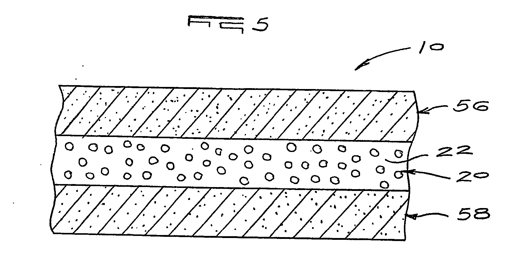
[0052] In the drawings, a geotechnical barrier in accordance with the invention is indicated generally by reference numeral 10.

[0053] The barrier 10 is used to inhibit contamination of the environment surrounding a waste site 12. The waste site 12 is prepared by providing a containment structure 14, generally in the form of a dam. A substrate 16 is prepared for laying of the geotechnical barrier 10.

[0054] In the embodiment shown in FIGS. 1 to 4, the geotechnical barrier 10 is a geosynthetic barrier comprising a first, under membrane 18 of a plastics material which is laid upon the substrate 16, to conform to the contours of the containment structure 14. Once the under membrane 18 is in place and the seams thereof have been welded or otherwise adhesively sealed, a drainage layer 20 is laid upon the under membrane 18. The drainage layer 20 comprises a stone aggregate 22. However, it will be appreciated that the drainage layer 20 may be provided by means of a geospacer, such as a net...


PUM


Abstract

A geotechnical barrier includes a first barrier layer; a second barrier layer overlying the first barrier layer and spaced therefrom, the first and second barrier layers defining, at least in part, a fluid passageway having an inlet and an outlet; and fluid displacement means for displacing a fluid through said fluid passageway from the inlet to the outlet. The invention extends to method for constructing and operating a geotechnical barrier and to a geosynthetic barrier and a geocomposite geosynthetic barrier.

Description

FIELD OF THE INVENTION [0001] This invention relates to a barrier and to a method for constructing and operating a barrier. In particular, the invention relates to a geotechnical barrier and method for constructing and operating such a barrier. The invention relates particularly, but not exclusively, to a geotechnical barrier for use in landfill sites, waste sites, and the like. BACKGROUND TO THE INVENTION [0002] Large-scale barrier systems which consist of several layers of geotechnical or geosynthetic materials each having varying liquid and gas permeability characteristics are well known. Such barrier systems are, typically, used to prevent or at least inhibit contamination of an underlying substrate and, consequently, of groundwater in the region of landfill and similar sites by toxic or dangerous waste products, which are either stored in the waste site or generated by the material dumped in the waste site. [0003] In many instances geosynthetic clay liners (“GCL”) are used in c...

Claims


Application Information

Patent Timeline
IPC IPC(8): B09B1/00E02D31/00
CPCE02D31/004
Inventor LEGGE, KELVIN ROBERTMEYER, PETRUS JOHANNES
Owner AQUATAN
Why Eureka
Eureka Blog
Learn More