Fluid end for a plunger pump

Active Publication Date: 2006-01-05
DIXIE IRON WORKS
View PDF8 Cites 64 Cited by
  • Summary
  • Abstract
  • Description
  • Claims
  • Application Information

AI Technical Summary

Benefits of technology

[0005] In view of the foregoing and other considerations, the present invention relates to reciprocating pumps. In particular it is a desire of the present invention to reduce the stresses encountered in fluid ends having a intersecting bores. It is a further desire to provide

Problems solved by technology

High stresses on the fluid ends of these pumps are associated with these high pressures.
Due to space limitation at transport equipment and well sites reduced profile pumps and equipment are desired.
While these configurations may provide a reduced profile they also produce a high stress regi

Method used


Image

  • Fluid end for a plunger pump
  • Fluid end for a plunger pump
  • Fluid end for a plunger pump

Examples


Example

[0017] Refer now to the drawings wherein depicted elements are not necessarily shown to scale and wherein like or similar elements are designated by the same reference numeral through the several views.

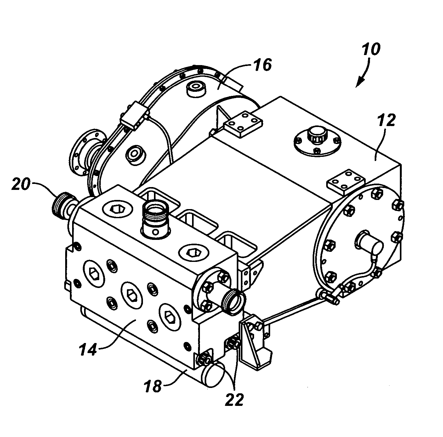
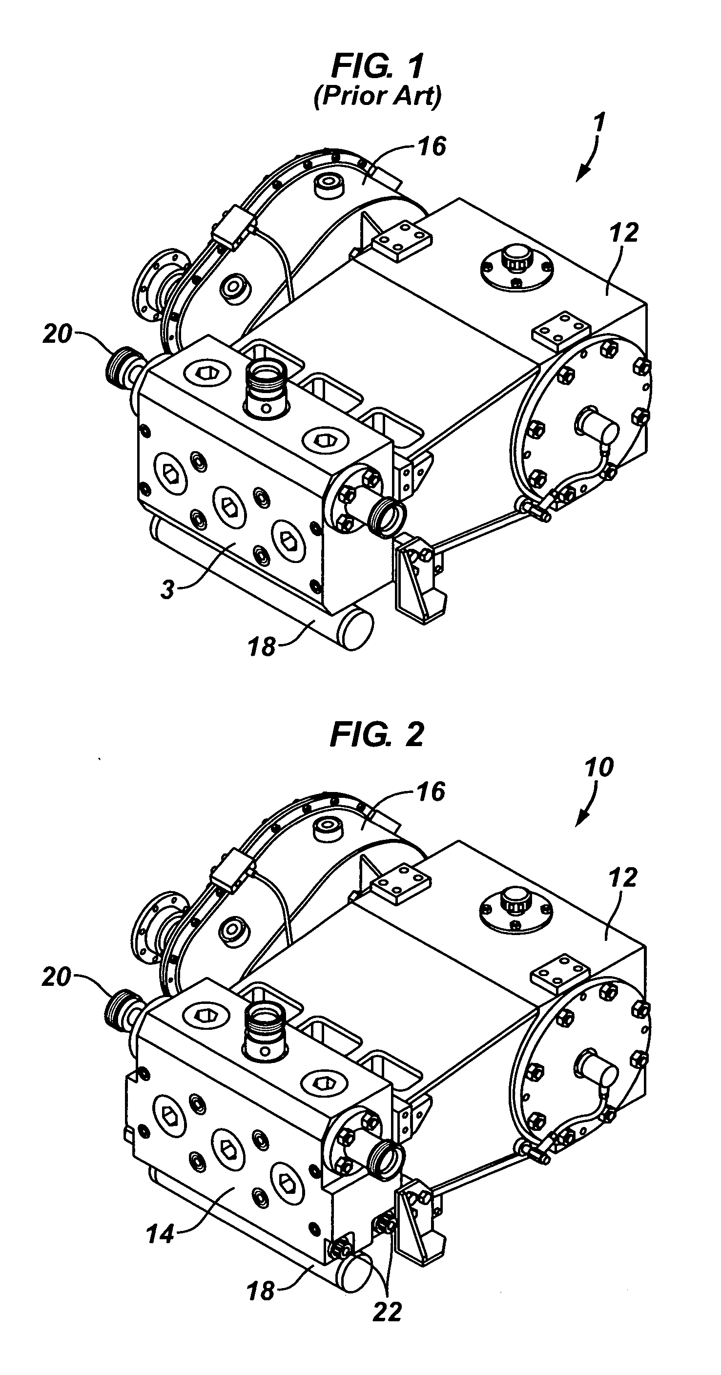
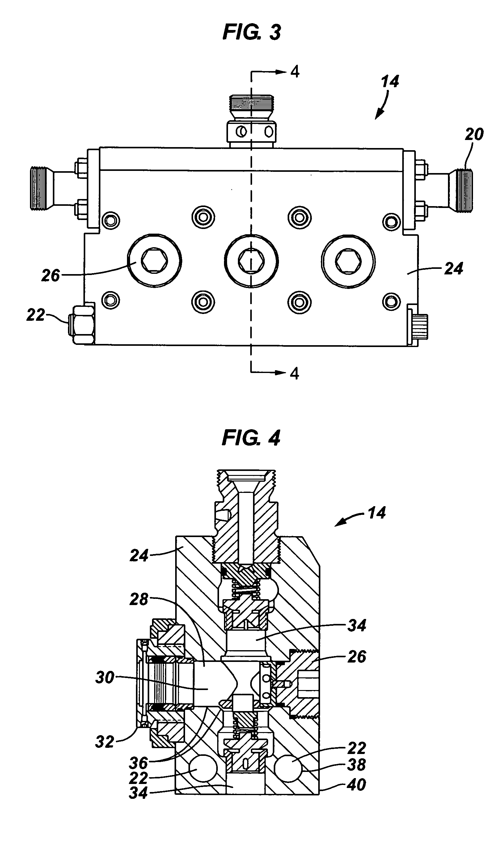
[0018]FIG. 1 is a perspective view of a prior art reciprocating plunger pump of the present invention, generally denoted by the numeral 1. Pump 1 is a typical, high-pressure, reciprocating fluid pump. Pump one comprises three primary portions, a power end 12, fluid end 3 and gear works 16. The power end 12 is conventional and contains a crankshaft, connecting rods, and various machinery required to reciprocate a plunger within the bore and cylinder of fluid end 14. The fluid end includes a suction intake manifold 18 and discharge ports 20.

[0019] As will be described in more detail with reference to the Figures of the present invention, the prior art fluid end 3 is susceptible to fatigue stresses that result in failure of pump 1 requiring expensive repairs and more often replacement....


PUM


Abstract

A fluid end for a reciprocating pump including a body having a base, a side and a longitudinal opposing side, a cylinder bore formed horizontally through the body and a vertical bore intersecting the cylinder bore defining a high stress region proximate the intersection, and a tension member extending through the body substantially parallel to the longitudinal axis of the body, wherein the tension member provides a compressive load on the body reducing the stresses encountered in the region during operation of the fluid end.

Description

RELATED APPLICATIONS [0001] This application is related to and claims priority to U.S. Provisional Application, Ser. No. 60 / 584,889, filed on Jul. 1, 2004.FIELD OF THE INVENTION [0002] The present invention relates in general to pumps and more specifically to the fluid end of plunger pumps. BACKGROUND [0003] High-pressure, reciprocating, plunger pumps have been used for many years and are a mainstay in the well services industry. These well service pumps often produce pressurized fluid in excess of 15,000 pounds per square inch. High stresses on the fluid ends of these pumps are associated with these high pressures. [0004] Due to space limitation at transport equipment and well sites reduced profile pumps and equipment are desired. Therefore, a popular fluid end has an intersecting horizontal cylinder bore and vertical bore. While these configurations may provide a reduced profile they also produce a high stress region proximate the intersection of the bores that suffers fatigue fai...

Claims


Application Information

Patent Timeline
IPC IPC(8): F04B53/10F04B39/10
CPCF04B39/10
Inventor BAXTER, WINSTON KIRKRICHARDS, MICHAEL STUART
Owner DIXIE IRON WORKS
Why Eureka
Try Eureka